


Hardware components | ||||||
| × | 1 | ||||
| × | 1 | ||||
Hand tools and fabrication machines | ||||||
 |
| |||||
 |
| |||||
Around 7 years ago, Killawhat uploaded to Instructables a Signal Generator that he built from a couple of kits he purchased from eBay. At the time I purchased the two kits with the intention to make it. However due to issues around getting the Interlock Push Button Switches, the project was shelved and forgotten about.
Recently I found the switches on Ali-Express and resurrected the project making some minor changes from the original on the way. Here is my build:
ICL8038 Signal Generator KitThis kit requires assembly. In my build, I was only interested in outputting a Sine wave.
I replaced the 4 potentiometers with 3-Pin Male Headers (Plain or KF2510). For the offset and duty cycle 5k potentiometers, I used 10-turn trim-pots as these weren't needed on the front panel. The Level and Frequency potentiometers are replaced with panel mount versions as shown below. The knobs for both potentiometers are 3D printed.
As mentioned, the switches are available from Ali-Express.
Because they don't come with button tops, I designed a 3D printed version (STL files attached).
For the button that switches the BNC socket to either be an output for the Oscillator or input for the Frequency Counter, I used a 8x8mm 6-Pin DPDT Self locking push switch.
Again, to keep consistency with the other buttons, the button top is 3D printed (STL file attached).
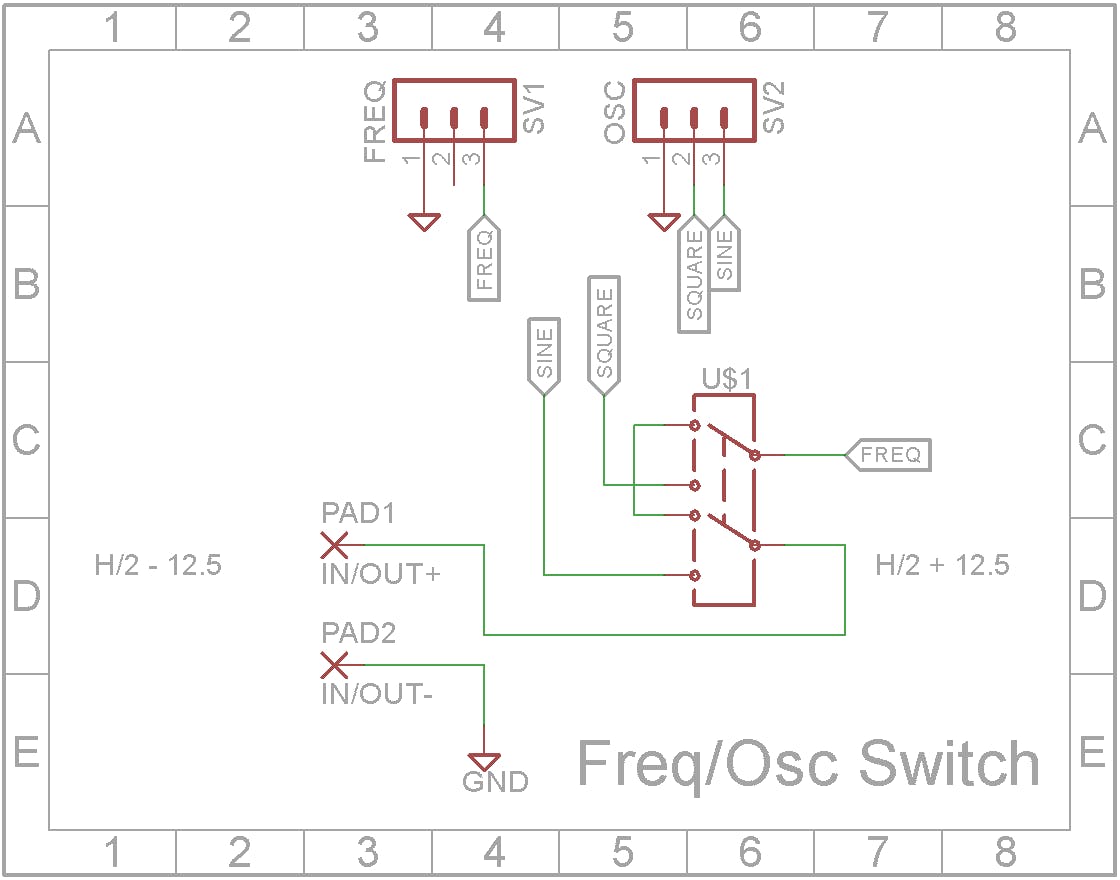
The output of the Oscillator is shared with the Frequency Counter. A switch switches between the BNC connector being used as a input to the Frequency Counter (no Oscillator output) and it being used as the output from the Oscillator in which case the Frequency Counter is measures the frequency of the Oscillator.
The Frequency Counter is quite frankly shocking when it comes to measuring the frequency of a Sine wave. It is great when measuring Square waves so when the switch is pressed, the BNC connector is connected to the Sine wave output from the Oscillator and the Frequency Counter is connected to the Square wave output from the Oscillator.
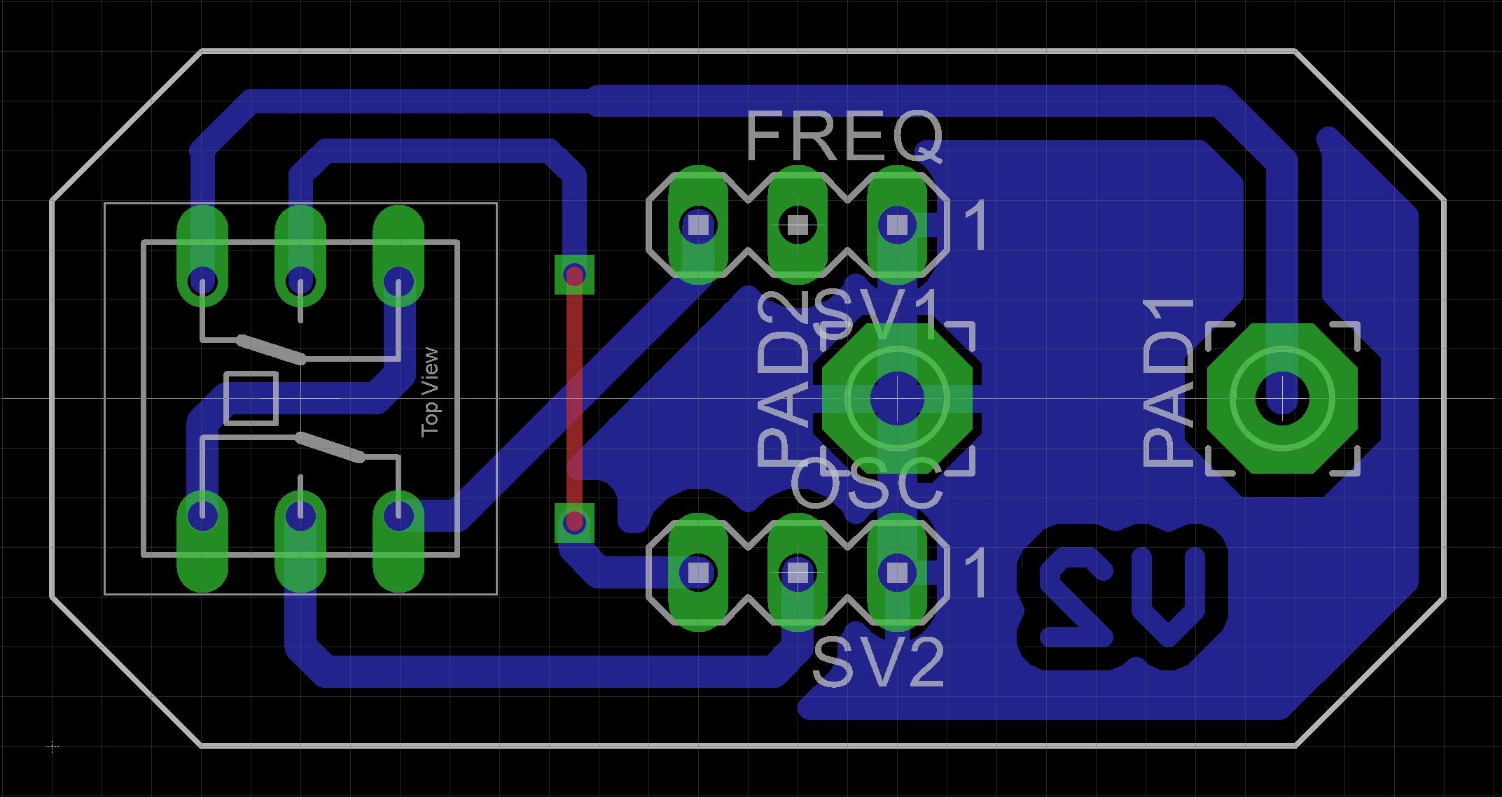
To facility this functionality, I designed a small board to hold the switch and the BNC connector.
I have included the Eagle files in case you want to get the board commercially made or do as I did and make it yourself. I used the Toner method.
Frequency CounterThe Frequency Counter comes either pre-built or as a kit. It features a 5 digit display. As mentioned before, on a clean Square wave it is quite accurate but degrades considerability on a non-square waveform. I covered this problem in my ATtiny1614 Frequency Meter project.
When assembling the kit, leave off the BNC connector, On/Off switch and DC power Socket. Add two pin KF2510 straight male connectors to where the BNC connector goes and also where C8 goes. C8 was soldered to where the DC power connector normally goes.
Replace the 16 pin straight male header with a 16 pin right-angle male header on the display board. Also solder the 16 pin female pin header on the underside of the CPU board. This allows the two PCBs to be connected at a right angle to each other.
I would recommend painting the sides between the 7 segment display modules with matt back paint so that the white sides don't show through.
Final assemblyThe case is 3D printed using a 0.2mm layer height. When printing "Osc - Text.stl", change to a contrasting color filament at the start of layer 4.
Add the WXD3 5K Potentiometer to "Osc - Front.stl" before joining "Osc - Text.stl" using double-sided tape. After the two parts are joined, you can add the rest of the front panel parts.
The 8038 Oscillator and Frequency Counters boards are screwed onto the case's top clam-shell using M3 6mm screws.
The quality of the Sine wave from the ICL8038 Oscillator is not good. The Frequency Counter can't measure low frequencies with any accuracy. The input stage for the Frequency Counter deteriorates badly on any waveform other than a pure square wave. I wouldn't recommend this project as a useful tool for your workshop.


Comments