

Hardware components | ||||||
| × | 1 | ||||
Software apps and online services | ||||||
 |
| |||||
Hand tools and fabrication machines | ||||||
 |
| |||||
 |
| |||||
Over the years, I have build a number of audio oscillator circuits using discreet components (no microprocessors). While these produce good quality sine waves, the frequency of the output is usually set by a simple marked-up dial. In audio work, precise frequency control isn't really required. Some more advanced oscillators showed the frequency on a meter but these are bulky solutions. All I really required was a small 5-Digit frequency meter preferably no bigger than the display itself so it took up as little room as possible.
Looking at different frequency meters on the eBay etc, I had mixed results with both their accuracy and what type of waveform they can reliably measure.
While all of them will perform as advertised provided you feed them a clean square wave, they start to show their limitations when feed other waveforms or when the signal is noisy or low in amplitude. This is due to the amplifier / buffer / wave shaping analog circuitry that feeds the microprocessor.
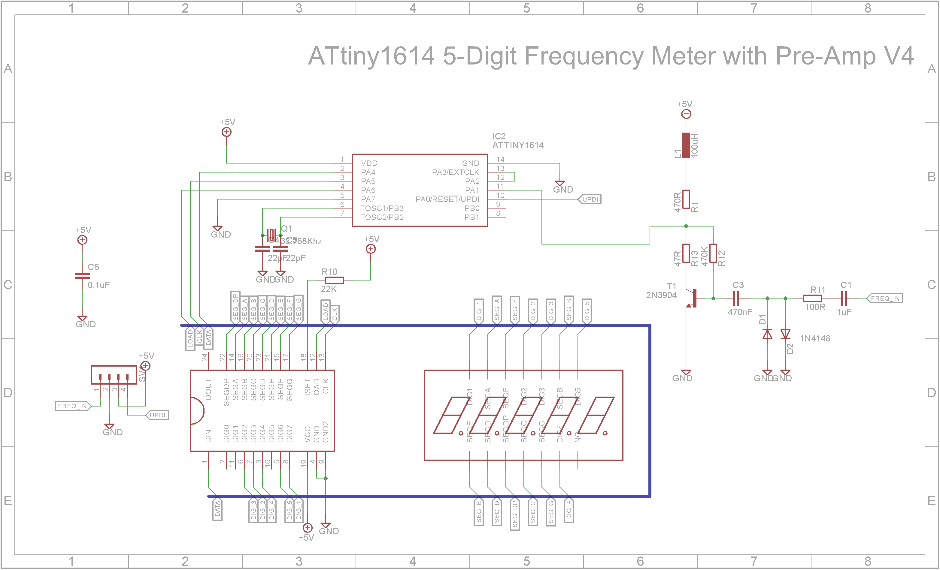
Building a frequency meterMy requirement was to have a 5-digit frequency meter (20Hz - 20kHz) on as small as possible board. The ATtiny1614 microprocessor is a cheap 14 pin SOIC chip with 16K Flash and 2K RAM running at up-to 20MHz. A 5 Digit 7-Segment display is driven by a MAX7219 driver chip. Also I added the input stage from DIY Simple Frequency Meter Up to 6.5MHz by Mirko Pavleski.
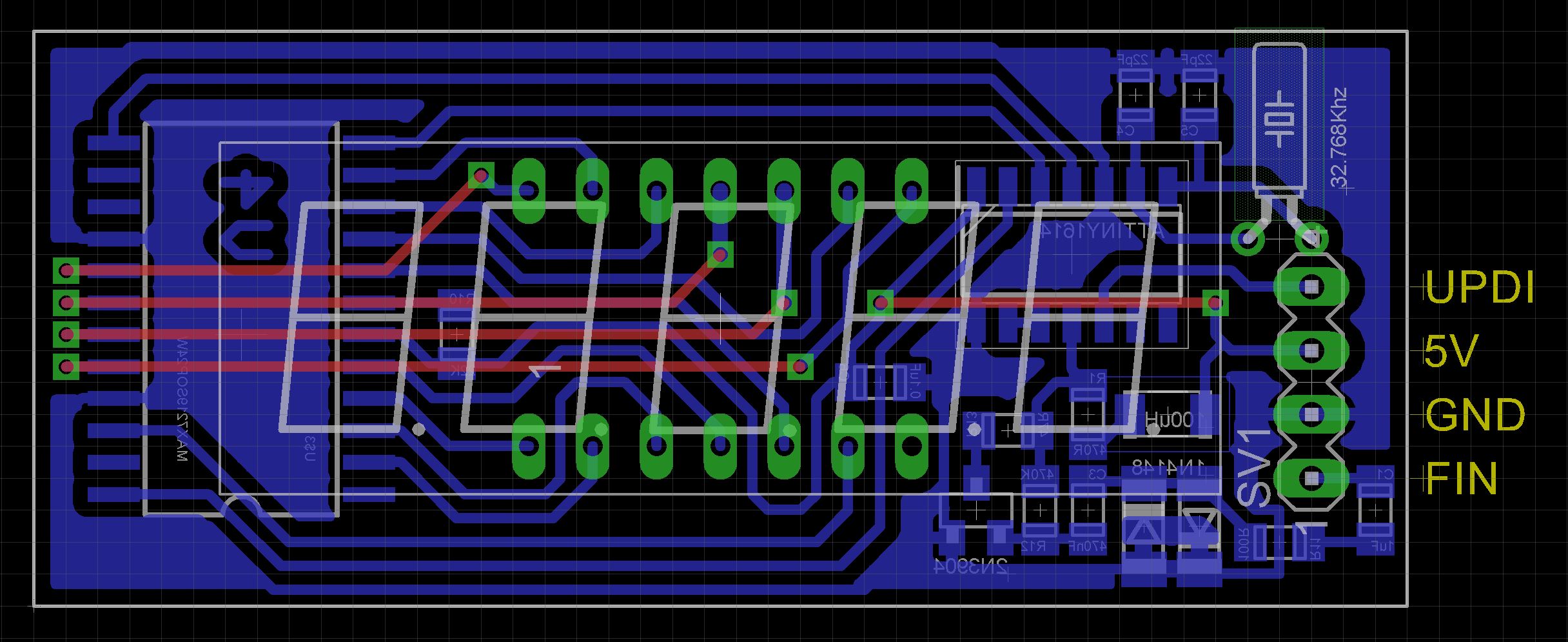
Except for the display and 32.768kHz crystal, the board that I designed uses SMD components exclusively. The Eagle files are included in case you want to get the board commercially made or you can make it yourself. I used the Toner method to make mine.
Start by adding the SMD components. I find it easier to use solder paste rather than use solder from a reel when soldering SMD components.
Add the links if your board is single sided.
Next add the headers. If your board has through hole plating, you can solder the wires directly to the board rather than use a connector. If you use a header on a single sided board, here is the method I use to add them.
Place header on PCB with longer pin side down, solder pins, push black plastic down towards the PCB.
Next add the display and 32.768kHz crystal to the top-side of the board.
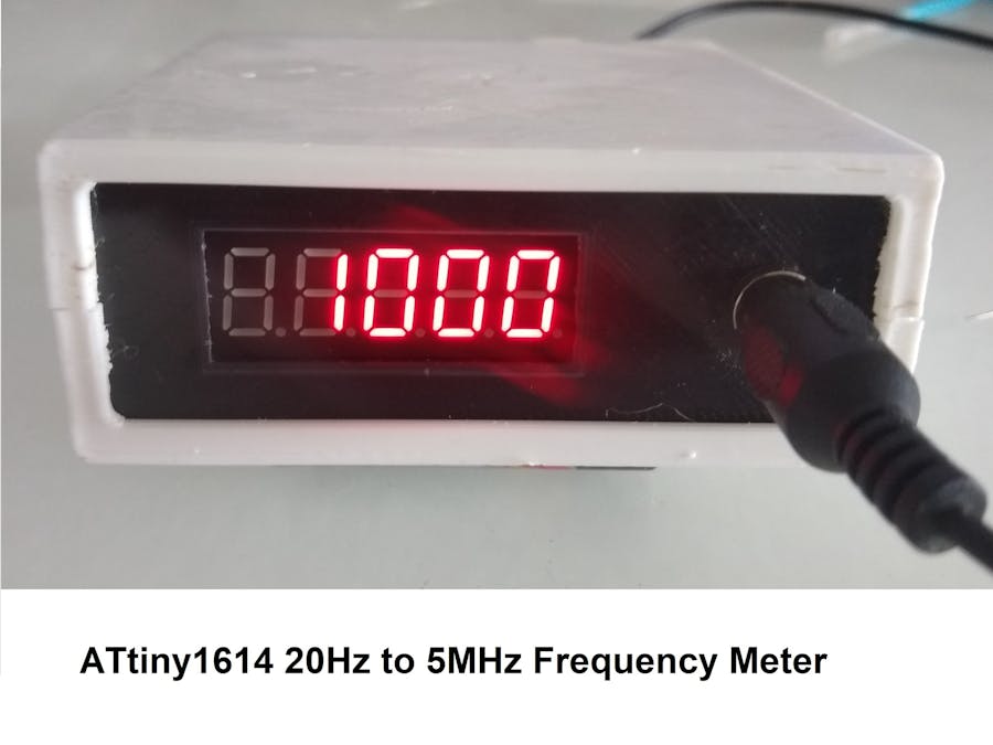
Recently David Johnson-Davies published a 100MHz frequency counter on his site Technoblogy. I modified his code to use a 5 Digit 7-Segment display instead of an OLED screen. One of the problems with 7-Segment displays is there is no sequence of segments that show the letter "k" for kilohertz. In this case I decided to use the "H". Frequencies above 99999Hz will be divided by 1000 and shown as below.
Unlike the earlier ATtiny series such as the ATtiny85, the ATtiny1614 uses the RESET pin to program the CPU. To program it you need a UPDI programmer. I made one using a Arduino Nano. You can find complete build instructions at Create Your Own UPDI Programmer. It also contains the instructions for adding the megaTinyCore boards to your IDE.
Once the board has been installed in the IDE, select it from the Tools menu.
Select the ATtiny1614 board in your IDE
Select Board, chip, clock speed, COM port the Arduino Nano is connected and the programmer
The Programmer needs to be set to jtag2updi (megaTinyCore).
Open the sketch and upload it to the ATtiny1614.
ResultsUnfortunately this design, like those kits on the market, suffer the same problem. Using a clean square wave, it displays the correct frequency with a reasonable accuracy. When feed a sine wave, the amplitude had a big impact on what the frequency meter showed. It needed at least 3V ptp. Also at low frequencies (under 50Hz), the accuracy suffered. This is all down to the input stage which also suffers from having a fairly low impedance. A low impedance can drag down the circuit being measured.
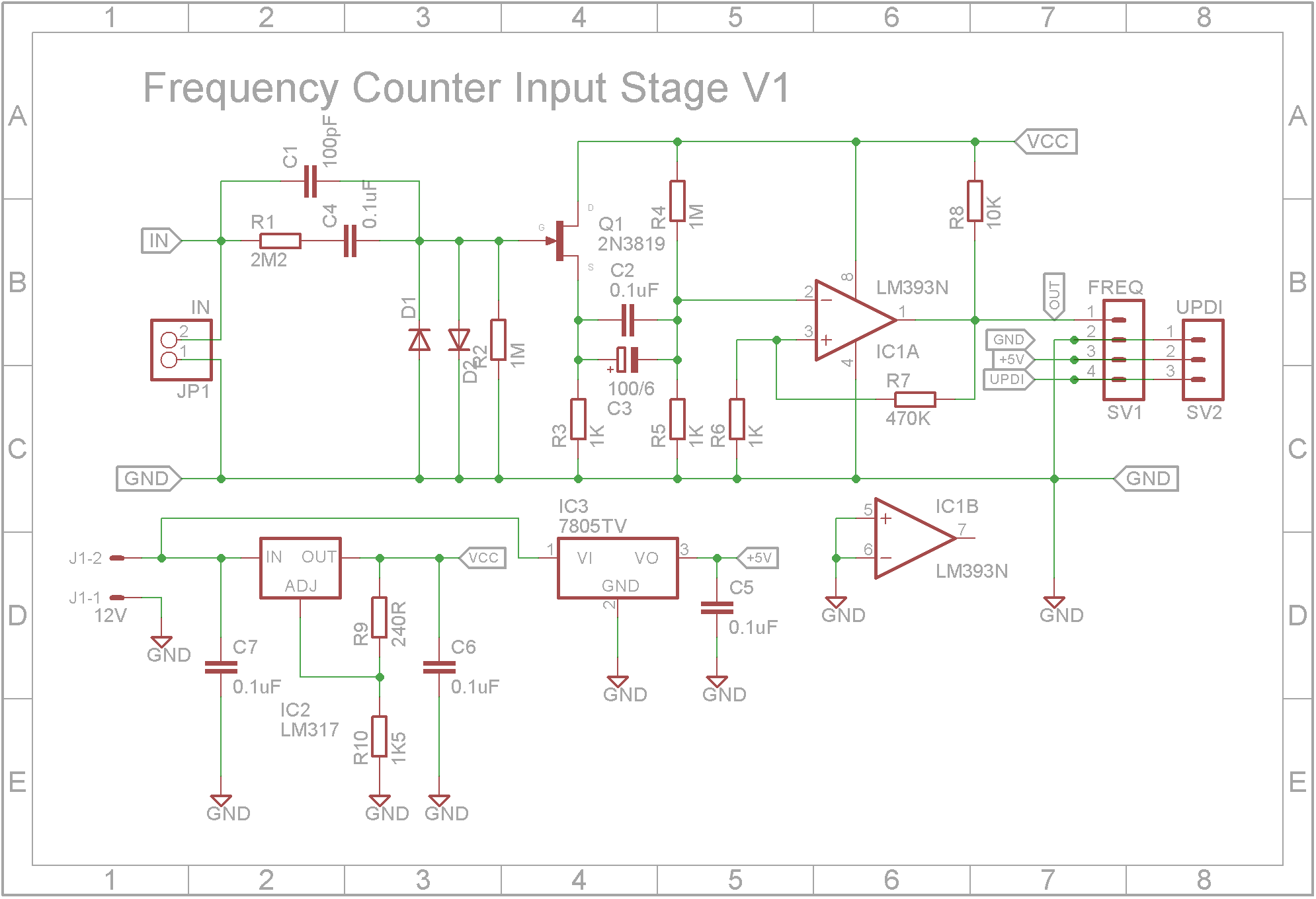
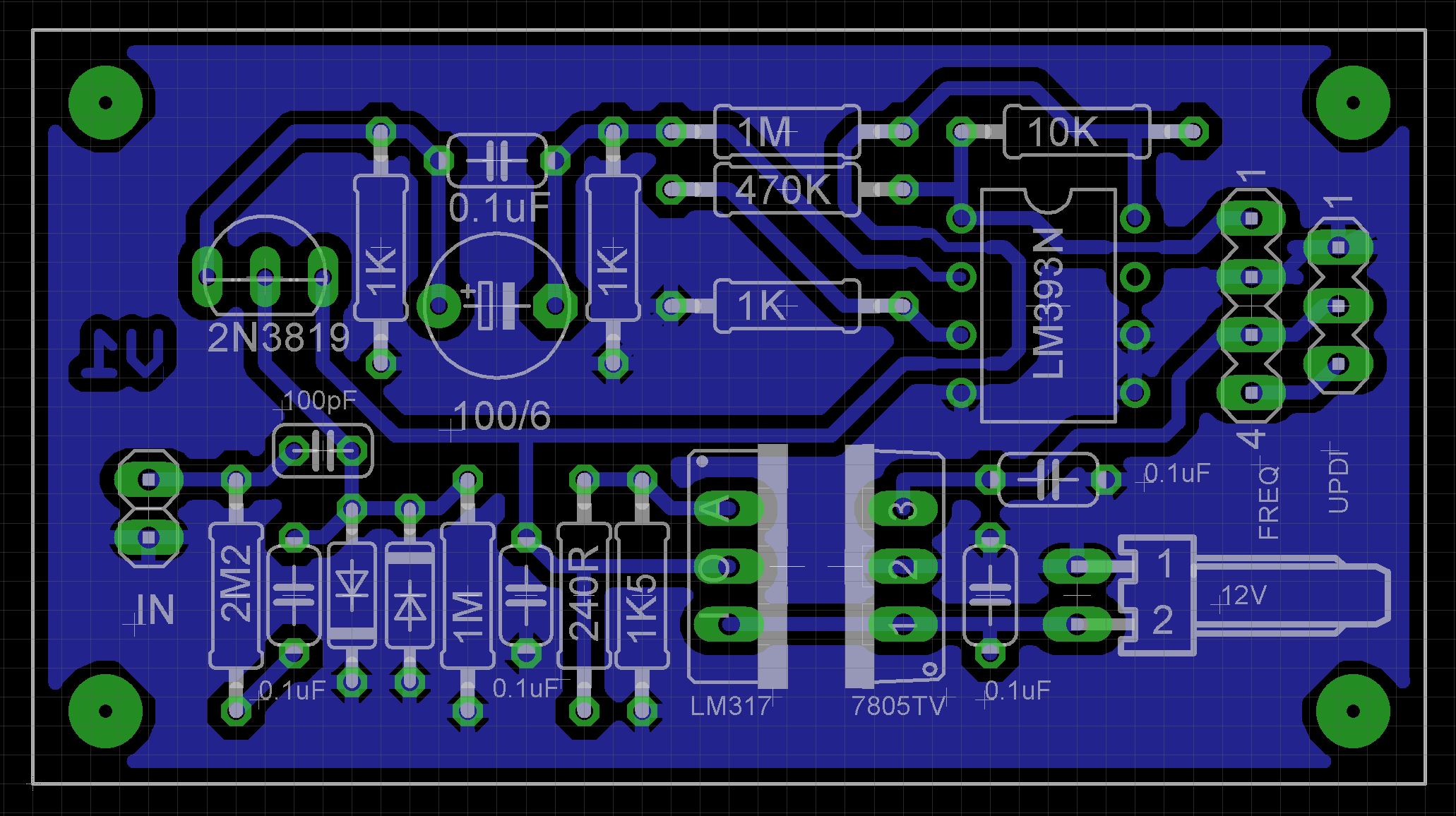
Improving the input stageSince the input stage on the Display board works fine on clean square waves, I decided not to remove it but to create a new input stage on a separate board. This would allow me to try different circuits. I found a circuit on the Internet called SOUND FREQUENCY METER and decided to try using its input stage. The schematic is shown below along with 5V and 9V regulators. (I used an adjustable regulator for the 9V supply because I didn't have a 7809 fixed 9V regulator on hand).
The STL files are included. Either take these to a 3D print shop or if you have your own printer, run them through your slicing software. I used a 0.2mm layer height and they need orientating in your slicing software.
On the base, drill out the four PCB mounting holes with a 2.5mm drill and create a thread with a 3mm tap.
The lugs that hold the shells together are a bit fragile. I glued on washers before I drilled the holes with a 2.5mm drill and created a thread with a 3mm tap. Drill out the holes that the screws go through with a 3mm drill.
The output board uses through hole components exclusively. I used a polarized header for the power connector and pin headers for the other connectors. Use a dab of red paint on the male pin headers to show which end the red wire goes to as the plugs can go in either way round.
Once tested, screw on the top using 6mm M3 screws.
The input stage has an upper limit of just over 5MHz. So this frequency meter works well from 20Hz to 5MHz on a 500mV or higher sine wave. The unit however is bigger than I originally wanted. I have a couple more input stages to test and then hopefully take the best one and add it to the display board with SMD components.


Comments