

Hardware components | ||||||
 |
| × | 1 | |||
Software apps and online services | ||||||
| ||||||
 |
| |||||
----------------------------------------------------------------------------------------------------------------
Link: Schematic: https://www.avnet.com/opasdata/d120001/medias/docus/193/Ultra96-V2%20Rev1%20Schematic.pdf
Board files: https://github.com/Avnet/bdf
----------------------------------------------------------------------------------------------------------------
ObjectiveThe objective of this module is to turn on [High] and off [Low] LEDs of the Ultra96 EMIO LEDs from jupyter notebook whilst using the PYNQ. PYNQ is a framework that allows the user to interface with hardware functions & foundations, from high-level languages such as python to the FPGA. It is bridging the gap from software developers to hardware developers, it is a drastic transformation from traditional design and testing. Within minutes a design can be verified, asserted, and used, making PYNQ the fastest most practical method in testing user applications.
This design follows the steps from creating a block design to mapping the constraints to then exporting the design to PYNQ. Furthermore, the application is then translated into the user's notebook, to then be configured and controlled. The initial routing to the GPIO pins was occupied by bootup LEDs in the PS, the new design reroutes the pins to the PL which then can be controlled and interfaced over PYNQ. The overlay reconfigures the path of the LEDs if you like.
----------------------------------------------------------------------------------------------------------------
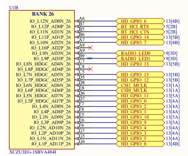
LEDs PS/PLThe schematic below provides a reference of the pins for the Ultra96. Our objective is to "highjack"/map RADIO_LED0 [A9] & RADIO_LED1 [B9] GPIO pins, since there are no GPIO LED pins given on the evaluation board strictly for PL use.
Per the image below, the pin assignment A9 and B9 are sufficient pins to now write the new Constraints. We see in BANK-26 there are IO pins that can be used. Let's now create the block diagram to insert these new findings
----------------------------------------------------------------------------------------------------------------
HW - Creating Block Diagram
Create a new project in Vivado with the correct requirements below, there is a question as to which silicon part we use. For this case and for the other parts of the series, the Ultra96-V2 version we are using is xczu3eg-sbva484-1-i.
- Create a Block Design
- Add IP - zynq_ultra_ps_e_0 & Run Automations
- Double Click, customize Zynq block & select IO configuration
- Locate IO peripherals and change GPIO EMIO - 2
- Right-click on the pin select on the GPIO_0 to external
- Hook up pl_clk0 to the maxihpm0_fpd_aclk & maxihpm1_fpd_aclk
- Create HDL Wrapper, right-click under sources "design_1"
- Add xdc, create a xdc constraints file
- Generate Bitstream
- Final Block Design
----------------------------------------------------------------------------------------------------------------
SW -Jupyiter NotebooksFiles Needed for Pynq file
- TCL - HW design
- BIT - Generate Bitstream
- HWH - Hardware Handler File
Use WinSCP to copy over the files to the ultra96 Linux service found in jupyter notebook. Refer to instructions to get started (https://pynq.readthedocs.io/en/v2.0/getting_started.html)
SW - Code#Import Libraries
import time
from pynq import Overlay, DefaultIP
from pynq import GPIO
#Parse in the overlay Ultra_96
overlay = Overlay("led_gpio_ps.bit")
overlay?
#PS LED Light Initialized - Blink
output= GPIO(GPIO.get_gpio_pin(0), 'out')
def led_blink():
output.write(1)
time.sleep(3)
print('Led = On')
#Toggle
output.write(0)
time.sleep(2)
print('Led = Off')
#Toggle
output.write(1)
time.sleep(2)
print('Led = On')
#Toggle
output.write(0)
time.sleep(3)
print('Led = Off')
led_blink()Led = On
Led = Off
Led = On
Led = OffAcknowledgments - Special Thanks
Mike Rockel
Adam Taylor
Xilinx <> AMD - ISM Team


Comments