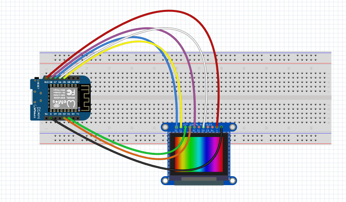
/*This Sample Sketch of Adafruit OLED ( SSD1351 ) is for ESP-WROOM-02 ( ESP8266).
* It does not work with Arduino UNO.
* Scavenged by Javier Muñoz javimusama@gmail.com, 22/12/2016
* ORIGINAL TUTORIAL FROM:(japanese) https://translate.google.com/translate?hl=en&sl=/auto&tl=en&u=https%3A%2F%2Fwww.mgo-tec.com%2Fblog-entry-adafruit-oled-ssd1351-esp-wroom-nonlib.html&sandbox=1
*///we dont need to include SPI.h to use it, arduino christmas magic
#define sclk 14 //WEMOS D5 pin
#define mosi 13 //WEMOS D7
#define cs 15 //WEMOS D8
const int DCpin = 4; //WEMOS D2
const int RSTpin = 5; //WEMOS D1
uint8_t bicho [16] ={0x0,0x0,0x66,0x7E,0x3C,0x18,0xFF,0x99,0x3C,0xFF,0xBD,0xBD,0x99,0x81,0x0,0x0};
uint8_t empty [16] = {0x00,0x00,0x00,0x00,0x00,0x00,0x00,0x00,0x00,0x00,0x00,0x00,0x00,0x00,0x00,0x00};//erases one character
uint8_t zero [16] = {0xff,0xff,0xc3,0xc3,0xc3,0xc3,0xc3,0xc3,0xc3,0xc3,0xc3,0xc3,0xc3,0xc3,0xff,0xff};//goes like a scanner
uint8_t one [16] = {0x18,0x18,0x18,0xf8,0xf8,0x18,0x18,0x18,0x18,0x18,0x18,0x18,0x18,0x18,0xff,0xff};//goes like a scanner
uint8_t two [16] = {0xff,0xff,0xc3,0xc3,0x03,0x03,0x03,0xff,0xff,0xc0,0xc0,0xc0,0xc3,0xc3,0xff,0xff};//goes like a scanner
uint8_t three[16] = {0xff,0xff,0x03,0x03,0x03,0x03,0x03,0xff,0xff,0x03,0x03,0x03,0x03,0x03,0xff,0xff};//goes like a scanner
uint8_t four [16] = {0xc3,0xc3,0xc3,0xc3,0xc3,0xc3,0xc3,0xff,0xff,0x03,0x03,0x03,0x03,0x03,0x03,0x03};//goes like a scanner
uint8_t five [16] = {0xff,0xff,0xc3,0xc3,0xc0,0xc0,0xc0,0xff,0xff,0x03,0x03,0x03,0xc3,0xc3,0xff,0xff};//goes like a scanner
uint8_t six [16] = {0xff,0xff,0xc3,0xc3,0xc0,0xc0,0xc0,0xff,0xff,0xc3,0xc3,0xc3,0xc3,0xc3,0xff,0xff};//goes like a scanner
uint8_t seven[16] = {0xff,0xff,0xc3,0xc3,0x03,0x03,0x03,0x03,0x03,0x03,0x03,0x03,0x03,0x03,0x03,0x03};//goes like a scanner
uint8_t eight[16] = {0xff,0xff,0xc3,0xc3,0xc3,0xc3,0xc3,0xff,0xff,0xc3,0xc3,0xc3,0xc3,0xc3,0xff,0xff};//goes like a scanner
uint8_t nine [16] = {0xff,0xff,0xc3,0xc3,0xc3,0xc3,0xc3,0xff,0xff,0x03,0x03,0x03,0x03,0x03,0x03,0x03};//goes like a scanner
//String numeros[10] = { "one", "two", "three","four","five","six","seven","eight","nine" };
uint8_t *pointernumeros[10];
//****************セットアップ*************************************************
void setup() {
Serial.begin(9600);
pointernumeros[0]=zero;
 pointernumeros[1]=one;
 pointernumeros[2]=two;
 pointernumeros[3]=three;
 pointernumeros[4]=four;
 pointernumeros[5]=five;
 pointernumeros[6]=six;
 pointernumeros[7]=seven;
 pointernumeros[8]=eight;
 pointernumeros[9]=nine;
pinMode(DCpin, OUTPUT);
pinMode(sclk, OUTPUT);
pinMode(mosi, OUTPUT);
pinMode(RSTpin, OUTPUT);
pinMode(cs, OUTPUT);
digitalWrite(cs, LOW);
digitalWrite(RSTpin, HIGH);
delay(500);
digitalWrite(RSTpin, LOW);
delay(500);
digitalWrite(RSTpin, HIGH);
delay(500);
SSD1351_Init();
delay(100);
SSD1351_BlackOut();
uint8_t Red = 31, Green = 63, Blue = 31; //Max Red = 31, Max Green = 63, MaxBlue = 31
int i=0;
Font1x1(i, 48, Red, 0, 0, zero);
i=i+10;
Font1x1(i, 48, Red, 0, 0, one);
i=i+10;
Font1x1(i, 48, Red, 0, 0, two);
i=i+10;
Font1x1(i, 48, Red, 0, 0, three);
i=i+10;
Font1x1(i, 48, Red, 0, 0, four);
i=i+10;
Font1x1(i, 48, Red, 0, 0, five);
i=i+10;
Font1x1(i, 48, Red, 0, 0, six);
i=i+10;
Font1x1(i, 48, Red, 0, 0, seven);
i=i+10;
Font1x1(i, 48, Red, 0, 0, eight);
i=i+10;
Font1x1(i, 48, Red, 0, 0, nine);
// Font1x1(8, 0, Red, Green, Blue, font_a[1]);
// Font2x2(0, 16, Red, Green, Blue, font_a[0]);
// Font2x2(16, 16, Red, Green, Blue, font_a[1]);
//
// Green = 0; Blue = 0;
// Font1x1(32, 32, Red, Green, Blue, font_a[0]);
// Font1x1(40, 32, Red, Green, Blue, font_a[1]);
//
// Red = 0; Green = 63; Blue = 0;
// Font2x2(48, 48, Red, Green, Blue, font_a[0]);
// Font2x2(64, 48, Red, Green, Blue, font_a[1]);
//
// Red = 0; Green = 0; Blue = 31;
// Font1x1(80, 80, Red, Green, Blue, font_a[0]);
// Font1x1(88, 80, Red, Green, Blue, font_a[1]);
//
// Red = 31; Green = 63; Blue = 20;
// Font2x2(96, 96, Red, Green, Blue, font_a[0]);
// Font2x2(112, 96, Red, Green, Blue, font_a[1]);
SSD1351_BlackOut();
}
//****************メインループ*************************************************
void loop() {
int i=random(0, 100);
int j=random(0, 100);
WriteNumber99(i,i,j,i-j,i*8,j);
// Font2x2(i, j, j, i-j, i*8, bicho);//bug rain
//THIS THING COUNTS 0-1000
// SSD1351_BlackOut();
// for(int y=0;y<10;y++){
// Font1x1(18, 48, 30, 63, 31, empty);
// Font1x1(18, 48, y*5, 63-y*5,0, pointernumeros[y]);
//
// for(int j=0;j<10;j++){
// Font1x1(30, 48, 30, 63, 0, empty);
// Font1x1(30, 48, y*5, 63-y*5, 0, pointernumeros[j]);
// delay(20);
// for(int i=0;i<10;i++){
// Font1x1(42, 48, 30, 63, 0, empty);
// Font1x1(42, 48, y*5, 63-y*5, 0, pointernumeros[i]);
//delay(20);
// }
// }
// }
}
//****************SSD1351初期化*************************************************
void SSD1351_Init(){
writeCommand(0xFD); //Set Command Lock
writeData(0x12); //Unlock OLED driver IC MCU interface from entering command
writeCommand(0xFD); //Set Command Lock
writeData(0xB1); //Command A2,B1,B3,BB,BE,C1 accessible if in unlock state
writeCommand(0xAE); //Sleep mode On (Display OFF)
writeCommand(0xB3); //Front Clock Divider
writeCommand(0xF1); // 7:4 = Oscillator Frequency, 3:0 = CLK Div Ratio (A[3:0]+1 = 1..16)
writeCommand(0xCA); //Set MUX Ratio
writeData(127);
writeCommand(0xA0); //Set Re-map
writeData(B01110100); //65k color
//writeData(B10110100); //262k color
//writeData(B11110100); //262k color, 16-bit format 2
writeCommand(0x15); //Set Column
writeData(0); //start
writeData(127); //end
writeCommand(0x75); //Set Row
writeData(0); //start
writeData(127); //end
writeCommand(0xA1); //Set Display Start Line
writeData(0);
writeCommand(0xA2); //Set Display Offset
writeData(0);
writeCommand(0xB5); //Set GPIO
writeData(0);
writeCommand(0xAB); //Function Selection
writeData(0x01); //Enable internal Vdd /8-bit parallel
//writeData(B01000001); //Enable internal Vdd /Select 16-bit parallel interface
writeCommand(0xB1); //Set Reset(Phase 1) /Pre-charge(Phase 2)
//writeCommand(B00110010); //5 DCLKs / 3 DCLKs
writeCommand(0x74);
writeCommand(0xBE); //Set VCOMH Voltage
writeCommand(0x05); //0.82 x VCC [reset]
writeCommand(0xA6); //Reset to normal display
writeCommand(0xC1); //Set Contrast
writeData(0xC8); //Red contrast (reset=0x8A)
writeData(0x80); //Green contrast (reset=0x51)
writeData(0xC8); //Blue contrast (reset=0x8A)
writeCommand(0xC7); //Master Contrast Current Control
writeData(0x0F); //0-15
writeCommand(0xB4); //Set Segment Low Voltage(VSL)
writeData(0xA0);
writeData(0xB5);
writeData(0x55);
writeCommand(0xB6); //Set Second Precharge Period
writeData(0x01); //1 DCLKS
writeCommand(0x9E); //Scroll Stop Moving
writeCommand(0xAF); //Sleep mode On (Display ON)
}
//****************全画面消去*************************************************
void SSD1351_BlackOut(){
writeCommand(0x15); //Set Column
writeData(0x00);
writeData(127);
writeCommand(0x75); //Set Row
writeData(0x00);
writeData(127);
writeCommand(0x5C); //Write RAM
for(int i=0; i<128*128; i++){
writeData(0x00);
writeData(0x00);
//writeData(0x00); //262k colorの場合3バイト分送信
}
}
//****************等倍フォント表示*************************************************
void Font1x1(uint8_t StartX, uint8_t StartY, uint8_t Red, uint8_t Green, uint8_t Blue, uint8_t* buf){
int16_t i,j;
uint8_t RGBbit1, RGBbit2;
RGBbit1 = (Red<<3) | (Green>>3);
RGBbit2 = (Green<<5) | Blue;
writeCommand(0x15); //Set Column
writeData(StartX);
writeData(StartX+7);
writeCommand(0x75); //Set Row
writeData(StartY);
writeData(StartY+15);
writeCommand(0x5C); //Write RAM
for(i=0; i<16; i++){
for(j=7; j>=0; j--){
if(buf[i] & _BV(j)){
writeData(RGBbit1);
writeData(RGBbit2);
}else{
writeData(0);
writeData(0);
}
}
}
}
//****************倍角フォント表示*************************************************
void Font2x2(uint8_t StartX, uint8_t StartY, uint8_t Red, uint8_t Green, uint8_t Blue, uint8_t* buf){
int16_t i,j,ii;
uint8_t RGBbit1, RGBbit2;
RGBbit1 = (Red<<3) | (Green>>3);
RGBbit2 = (Green<<5) | Blue;
writeCommand(0x15); //Set Column
writeData(StartX);
writeData(StartX+15);
writeCommand(0x75); //Set Row
writeData(StartY);
writeData(StartY+31);
writeCommand(0x5C); //Write RAM
for(i=0; i<16; i++){
for(ii=0; ii<2; ii++){//倍角の場合2行同じものを描く
for(j=7; j>=0; j--){
if(buf[i] & _BV(j)){
writeData(RGBbit1);
writeData(RGBbit2);
writeData(RGBbit1);
writeData(RGBbit2);
}else{
writeData(0);
writeData(0);
writeData(0);
writeData(0);
}
}
}
}
}
//****************SPIデータ処理*************************************************
void SPIwrite(uint8_t c){
digitalWrite(sclk, HIGH);
int8_t i; //signed intでなければならない。負の数になると255という値になって、例外エラーになる。
for (i=7; i>=0; i--) {
digitalWrite(sclk, LOW);
if (c & _BV(i)) {
digitalWrite(mosi, HIGH);
} else {
digitalWrite(mosi, LOW);
}
digitalWrite(sclk, HIGH);
}
}
void writeCommand(uint8_t c) {
digitalWrite(DCpin, LOW);
digitalWrite(cs, LOW);
SPIwrite(c);
digitalWrite(cs, HIGH);
}
void writeData(uint8_t c) {
digitalWrite(DCpin, HIGH);
digitalWrite(cs, LOW);
SPIwrite(c);
digitalWrite(cs, HIGH);
}
////////////////////Write number 00 Up to to 99
void WriteNumber99(int number,int x,int y,int red,int green, int blue){
 int unit=0;
 int dec=0;
dec=number/10;
unit=number-(dec*10);
Serial.print(dec);
 Serial.print(" ");
 Serial.println(unit);
 Font1x1(x, y+32,red, green,blue, pointernumeros[dec]);
 Font1x1(x+12, y+32,red, green,blue, pointernumeros[unit]);
}
////////////////////Write number 00 Up to to 999
void WriteNumber999(int number,int x,int y,int red,int green, int blue){
int unit=0;
int dec=0;
int cent=0;
cent=number/100;
dec=(number-(cent*100))/10;
unit=number-(dec*10)-(cent*100);
Serial.print( cent);
Serial.print( " ");
Serial.print( dec);
Serial.print( " ");
Serial.println( unit);
Font1x1(x, y+32,red, green,blue, pointernumeros[cent]); //y has a offset of 32 because the code is for 128pixel screen
Font1x1(x+12, y+32,red, green,blue, pointernumeros[dec]);
Font1x1(x+24, y+32,red, green,blue, pointernumeros[unit]);
}


Comments