

Hardware components | ||||||
 |
| × | 1 | |||
| × | 1 | ||||
Software apps and online services | ||||||
| ||||||
 |
| |||||
 |
| |||||
 |
| |||||
In industrial edge AI, a major challenge is isolating "probabilistic AI inference" and "non-deterministic Linux behavior" from safety-critical control systems.
This project leverages the AMD Zynq UltraScale+ MPSoC to create a single-chip architecture that balances high-performance AI processing with independent, deterministic Safety Monitoring powered by Zephyr RTOS.
This system partitions the Kria KV260 into a Performance Domain for AI recognition and a Safety Island for monitoring, creating a high-reliability edge AI device.
- AI Recognition: The Application Processing Unit (Cortex-A53) and Programmable Logic (DPU) perform advanced object detection.
- Safety Monitoring: Zephyr RTOS, running on the Real-time Processing Unit (Cortex-R5), constantly monitors the AI domain. It outputs a physical emergency stop signal if it detects AI misclassification or an OS freeze.
The design utilizes the hardware features of the Zynq UltraScale+ to achieve Freedom from Interference (FFI), a core requirement of functional safety standards.
- Target Board: Kria KV260 Vision AI Starter Kit
Processor Segmentation:
- PS (PetaLinux): Quad-core Cortex-A53 running PetaLinux to control the Vitis AI DPU for heavy image analysis.
- RPU (Real-time Processing Unit): Dual-core Cortex-R5 in Lock-step Mode. This unit runs Zephyr RTOS to handle high-reliability monitoring logic and I/O control. By running the RPU in lock-step mode, the system can detect and prevent computational errors at the hardware level.
- PL (Programmable Logic): The FPGA fabric hosts the DPU for AI acceleration and a dedicated, RPU-controlled GPIO for independent emergency shutdown.
The software employs a hybrid stack to achieve both inference efficiency and deterministic response times.
Safety Runtime (Zephyr RTOS on RPU): Using Zephyr optimized for Cortex-R5, we utilize the MPU (Memory Protection Unit) for task isolation.
Note on Configuration: The Cortex-R5 supports two operation modes: Split Mode (two independent cores with their own TCMs) and Lock-step Mode (a single unit with double the TCM size). In this project, we are currently testing with Split Mode.
- Application OS (PetaLinux on APU):PetaLinux drives the DPU via the Vitis AI runtime (VART), enabling high-speed inference for AI models such as YOLO.
- Inter-Processor Communication (OpenAMP):OpenAMP is used for communication between the APU and RPU. It synchronizes AI detection results and system status with low latency via shared memory.
- Health Monitoring (Heartbeat):The Zephyr-based RPU monitors a "Heartbeat" signal from the AI application. If the signal is lost or an abnormality is detected, it immediately sends a trigger to the safety circuit in the PL.
The first step is establishing a robust debug environment for the Cortex-R5 cores on the KV260. This begins with the initial setup of the PetaLinux environment, culminating in a successful "Hello World" execution to verify the base system.
- Leveraging the KV260’s support from Zephyr project, we plan to implement a safety runtime using Zephyr RTOS on the Real-time Processing Unit (RPU).
https://docs.zephyrproject.org/latest/boards/amd/kv260_r5/doc/index.html
First, install the latest PetaLinux environment. Note that for Ubuntu 24.04, some library adjustments might be necessary. Refer to AMD documentation for full installation details.
https://docs.amd.com/r/en-US/ug1144-petalinux-tools-reference-guide/Setting-Up-Your-Environment
# Example installer execution
chmod +755 ./petalinux-v2025.2-11160223-installer.run
./petalinux-v2025.2-11160223-installer.run -d /opt/petalinux/2025.2/
Download the KV260 Starter Kit BSP and create the project:
# Example create the project
petalinux-create -t project -s xilinx-kv260-starterkit-v2025.1-05221048.bsp
cd xilinx-kv260-starterkit-2025.1/To allow the R5 core to communicate and use UART from MicroUSB (ttyPS0), we need to modify the Device Tree and Kernel settings.
For First-time PetaLinux Login, we recommend enabling a serial console via a USB serial cable (ttyUSB0) in addition to SSH.
# Example Kernel & Device Tree Configuration
petalinux-config -c kernel
petalinux-config
1. USB Serial Driver:Enable FTDI or relevant USB-Serial drivers in the kernel (petalinux-config -c kernel) to allow PetaLinux to use an external USB-serial cable for its own console, freeing up the onboard UART for Zephyr.
To keep the hardware active for Zephyr, add clk_ignore_unused to the kernel bootargs. You can find this under "DT Settings > Kernel Bootargs" in petalinux-config.
2. Modify system-user.dtsi: We need to define the reserved memory for the RPU (Remote Processor Unit) and configure the IPI (Inter-Processor Interrupt) mailboxes.
- Reserved memory regions (vring, buffer, rproc)
- Enable TCM (Tightly Coupled Memory)
- Define the r5fss cluster mode
/xilinx-kv260-starterkit-2025.1/project-spec/meta-user/recipes-bsp/device-tree/files/system-user.dtsi
/include/ "system-conf.dtsi"
/ {
      chosen {
          bootargs = "console=ttyUSB0,115200 root=/dev/ram0 rw init_fatal_sh=1 cma=900M clk_ignore_unused";
      };

      reserved-memory {
      #address-cells = <0x02>;
      #size-cells = <0x02>;
      ranges;

      rpu0vdev0vring: rpu0vdev0vring0@3ed40000 {
          no-map;
          reg = <0x00 0x3ed40000 0x00 0x4000>;
      };

      rpu0vdev0vring1: rpu0vdev0vring1@3ed44000 {
          no-map;
          reg = <0x00 0x3ed44000 0x00 0x4000>;
      };

      rpu0vdev0buffer: rpu0vdev0buffer@3ed48000 {
          no-map;
          reg = <0x00 0x3ed48000 0x00 0x100000>;
      };

      rproc: rproc@3ed00000 {
          no-map;
          reg = <0x00 0x3ed00000 0x00 0x40000>;
      };
  };

  tcm_0a: tcm_0a@ffe00000 {
      reg = <0x0 0xffe00000 0x0 0x10000>;
      status = "okay";
      compatible = "mmio-sram";
      power-domains = <&zynqmp_firmware 15>;
  };

  tcm_0b: tcm_0b@ffe20000 {
      no-map;
      reg = <0x0 0xffe20000 0x0 0x10000>;
      status = "okay";
      compatible = "mmio-sram";
      power-domains = <&zynqmp_firmware 16>;
      };

  r5fss@ff9a0000 {
      compatible = "xlnx,zynqmp-r5fss";
      xlnx,cluster-mode = <1>;
      ranges;
      reg = <0x0 0xFF9A0000 0x0 0x10000>;
      status = "okay";
      #address-cells = <0x2>;
      #size-cells = <0x2>;

      r5f_0: r5f@0 {
          compatible = "xilinx,r5f";
          #address-cells = <0x2>;
          #size-cells = <0x2>;
          ranges;
          memory-region = <&rproc &rpu0vdev0buffer &rpu0vdev0vring &rpu0vdev0vring1>;
          power-domains = <&zynqmp_firmware 7>;
          mboxes = <&ipi_mailbox_rpu0 0>, <&ipi_mailbox_rpu0 1>;
          mbox-names = "tx", "rx";
                  tcm_0_a: tcm_0@ffe00000 {
                      reg = <0x0 0xFFE00000 0x0 0x10000>;
                      status = "okay";
                      compatible = "mmio-sram";
                      power-domains = <&zynqmp_firmware 15>;
                  };
                  tcm_0_b: tcm_0@ffe20000 {
                      reg = <0x0 0xFFE20000 0x0 0x10000>;
                      status = "okay";
                      compatible = "mmio-sram";
                      power-domains = <&zynqmp_firmware 16>;
                  };
             };
      };

  zynqmp_ipi1 {
      compatible = "xlnx,zynqmp-ipi-mailbox";
      interrupt-parent = <&gic>;
      interrupts = <0 29 4>;
      xlnx,ipi-id = <7>;
      #address-cells = <1>;
      #size-cells = <1>;
      ranges;

      /* APU<->RPU0 IPI mailbox controller */
      ipi_mailbox_rpu0: mailbox@ff990600 {
              compatible = "xlnx,zynqmp-ipi-dest-mailbox";
          reg = <0xff990600 0x20>,
                <0xff990620 0x20>,
                <0xff9900c0 0x20>,
                <0xff9900e0 0x20>;
          reg-names = "local_request_region",
                  "local_response_region",
                  "remote_request_region",
                  "remote_response_region";
          #mbox-cells = <1>;
          xlnx,ipi-id = <1>;
      };
  };
};
3. Disable UART1 in PetaLinux:In zynqmp-sck-kv-g-revB.dtso, set uart1 to disabled. This prevents the Linux kernel from claiming the UART hardware that Zephyr will use.
/xilinx-kv260-starterkit-2025.1/project-spec/dts_dir
&uart1 {
	status = "disabled";
	pinctrl-names = "default";
	pinctrl-0 = <&pinctrl_uart1_default>;
};Once the configuration is complete, proceed to build the system and generate the SD card image.
#Example petalinux-build
petalinux-build
petalinux-package --boot --u-boot --force
petalinux-package --wic --images-dir images/linux/ --bootfiles "ramdisk.cpio.gz.u-boot,boot.scr,Image,system.dtb,system-zynqmp-sck-kv-g-revB.dtb"
Flashing to SD Card:Locate the generated .wic file in the images/linux/ directory. Use a tool like balenaEtcher or the dd command to flash this image onto your microSD card.
Initial Boot and Login:Insert the microSD card into your KV260 and power it up. Connect to the board via your USB serial terminal (ttyUSB0) (e.g., PuTTY or screen) at 115200 baud.
********************************************************************************************
PetaLinux 2025.2+release-S11151021 xilinx-kv260-starterkit-20251 ttyUSB0

xilinx-kv260-starterkit-20251 login: petalinux
You are required to change your password immediately (administrator enforced).
New password:
Retype new password:
Apr 25 04:13:30 xilinx-kv260-starterkit-20251 kernel: kauditd_printk_skb: 14 callbacks suppressed
xilinx-kv260-starterkit-20251:~$
xilinx-kv260-starterkit-20251:~$ ls /
bin  boot  configfs  dev  etc  home  lib  lost+found  media  mnt  proc  root  run  sbin  srv  sys  tmp  usr  var
xilinx-kv260-starterkit-20251:~$
Note on Login: With PetaLinux 2025.2, the default username is petalinux. On your first login, the system will prompt you to set a new password immediately.Once logged in, you can also access the board via SSH over your local network for easier file transfers.
Using the Zephyr development environment, build the "Hello World" sample specifically for the kv260_r5 board. Please refer to the following for more details.
https://docs.zephyrproject.org/latest/boards/amd/kv260_r5/doc/index.html
My version (same as the official one) is also available below.
https://github.com/iotengineer22/zephyr-kv260/tree/main/src/zephyr/kv260_r5_hello_world
west build -p -b kv260_r5Upon successful build, you will get a zephyr.elf file in the build directory.
Once PetaLinux is booted on the KV260, transfer the zephyr.elf to the target (via SSH/SCP) and use remoteproc to load it onto the R5 core.
# Move firmware to the standard directory
sudo cp zephyr.elf /lib/firmware/

# Load and start the R5 core
sudo -i
echo zephyr.elf > /sys/class/remoteproc/remoteproc0/firmware
echo start > /sys/class/remoteproc/remoteproc0/state
Open your serial terminal (connected to the KV260 MicroUSB). You should see the following output:
*** Booting Zephyr OS build v4.4.0-1293-g81e1e71d3f90 ***
Hello World! kv260_r5/zynqmp_rpuBelow is the actual Demo Video.
5. Zephyr RTOS: PL (FPGA) InterfacingThis stage focuses on enabling communication and resource sharing between Zephyr RTOS, the Processing System (PS) running PetaLinux, and the Programmable Logic (PL) within the FPGA.
We will also verify the GPIO operation via the PMOD interface
First, create a design featuring AXI GPIO connected to the KV260 PMOD interface in Vivado. The Vivado project setup follows the same process as this article:
https://www.hackster.io/iotengineer22/control-gpio-from-pynq-and-kr260-0d3613
The tcl project files are available at the link below.
https://github.com/iotengineer22/zephyr-kv260/tree/main/src/fpga/zephyr_kv260_gpio/project
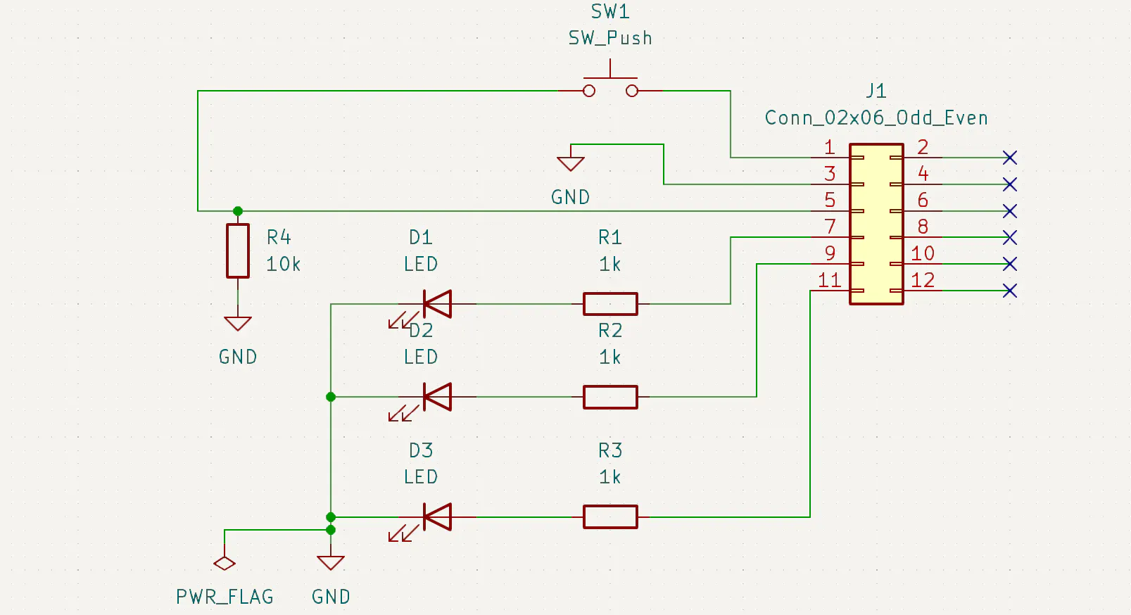
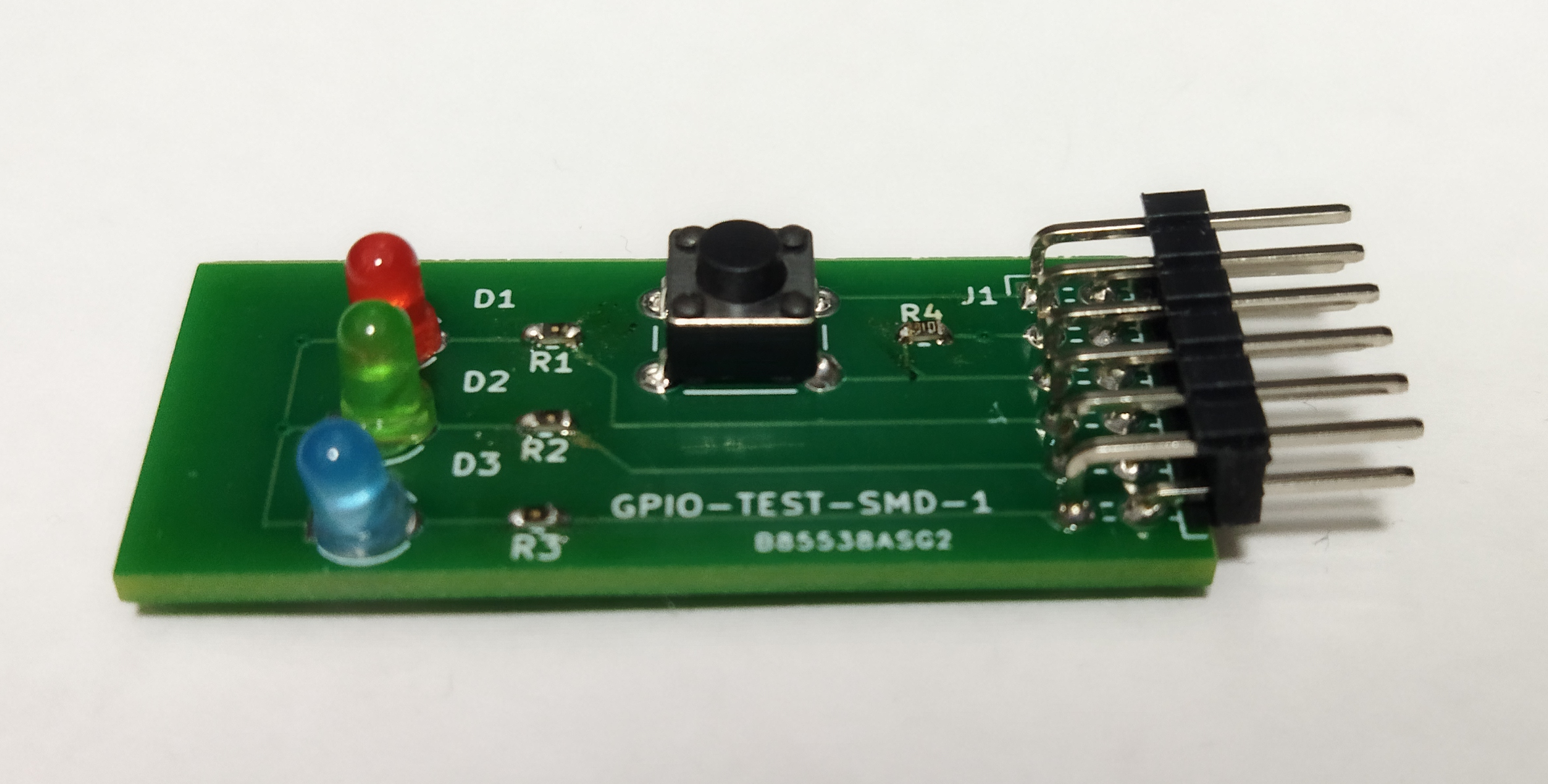
- XDC Constraints: Map the GPIO to the PMOD pins (e.g.,
H12,E10,D10,C11).
This address is configured for the LED/SW debug board connected to the KV260 PMOD.
https://github.com/iotengineer22/PCB-KV260-PMOD-TEST
set_property PACKAGE_PIN H12 [get_ports gpio_rtl_0_tri_o[0]]
set_property PACKAGE_PIN E10 [get_ports gpio_rtl_0_tri_o[1]]
set_property PACKAGE_PIN D10 [get_ports gpio_rtl_0_tri_o[2]]
set_property PACKAGE_PIN C11 [get_ports gpio_rtl_1_tri_i[0]]

set_property IOSTANDARD LVCMOS33 [get_ports gpio_rtl_0_tri_o[0]]
set_property IOSTANDARD LVCMOS33 [get_ports gpio_rtl_0_tri_o[1]]
set_property IOSTANDARD LVCMOS33 [get_ports gpio_rtl_0_tri_o[2]]
set_property IOSTANDARD LVCMOS33 [get_ports gpio_rtl_1_tri_i[0]]- Export Hardware: Generate the Bitstream and export the
.xsafile.
Kria uses xmutil for dynamic bitstream loading. You need three files: pl.dtbo, .bit.bin, and shell.json. The project files are available below.
https://github.com/iotengineer22/zephyr-kv260/tree/main/src/fpga/zephyr_kv260_gpio
- Device Tree Overlay (DTBO): Use Vitis
xsctto generate the overlay from your.xsa.
xsct
createdts -hw design_1_wrapper.xsa -zocl -platform-name mydevice -git-branch xlnx_rel_v2025.2 -overlay -compile -out mydevice
dtc -@ -O dtb -o mydevice/mydevice/mydevice/psu_cortexa53_0/device_tree_domain/bsp/pl.dtbo mydevice/mydevice/mydevice/psu_cortexa53_0/device_tree_domain/bsp/pl.dtsi
mkdir dtg_output
cp mydevice/mydevice/mydevice/psu_cortexa53_0/device_tree_domain/bsp/pl.dtbo dtg_output/- Bitstream Conversion: Convert the
.bitto.binusingbootgen
cd [Vivado project]/[Vivado project].runs/impl_1
echo 'all:{design_1_wrapper.bit}' > bootgen.bif
bootgen -w -arch zynqmp -process_bitstream bin -image bootgen.bif- shell.json: Define the accelerator type as
XRT_FLAT.
echo '{' > shell.json
echo ' "shell_type" : "XRT_FLAT",' >> shell.json
echo ' "num_slots": "1"' >> shell.json
echo '}' >> shell.jsonThis is the most critical part. By default, the R5 core cannot access the PL address space.
- Modify KV260 MPU Settings Edit
zephyr/soc/xlnx/zynqmp/arm_mpu_regions.cto allow access to the AXI region (starting at0x80000000). The project files are available below.
https://github.com/iotengineer22/zephyr-kv260/tree/main/src/zephyr/modify_zephyr_project
/* Allow access to the PL (FPGA) region */
	MPU_REGION_ENTRY(
		"PL_AXI",
		0x80000000,
		REGION_1G,
		{.rasr = P_RW_U_NA_Msk |
			 DEVICE_SHAREABLE |
NOT_EXEC}),- Device Tree Overlay (.overlay) Map the AXI GPIO in your Zephyr project. Note: Place the nodes under
&{/soc}to ensure 32-bit address mapping is handled correctly. The detail overlay files are available below.
/* SPDX-License-Identifier: Apache-2.0 */
#include <zephyr/dt-bindings/gpio/gpio.h>

/ {
    aliases {
        led0 = &led_0;
        led1 = &led_1;
        led2 = &led_2;
        sw0 = &sw_0;
    };

    leds {
        compatible = "gpio-leds";
        led_0: led_0 {
            gpios = <&axi_gpio_0 0 GPIO_ACTIVE_HIGH>;
        };
        led_1: led_1 {
            gpios = <&axi_gpio_0 1 GPIO_ACTIVE_HIGH>;
        };
        led_2: led_2 {
            gpios = <&axi_gpio_0 2 GPIO_ACTIVE_HIGH>;
        };
    };

    buttons {
        compatible = "gpio-keys";
        sw_0: button_0 {
            gpios = <&axi_gpio_1 0 GPIO_ACTIVE_HIGH>;
        };
    };
};

/*
 * Key point of the fix:
 * By describing it inside the &{/soc} node instead of the root,
 * the 32-bit address will be interpreted correctly.
 */
&{/soc} {
    axi_gpio_0: gpio@b0000000 {
        compatible = "xlnx,xps-gpio-1.00.a";
        /* Address 0xb0000000, size 0x10000 described with 1 cell each */
        reg = <0xb0000000 0x10000>;
        status = "okay";
        gpio-controller;
        #gpio-cells = <2>;
    };

    axi_gpio_1: gpio@b0010000 {
        compatible = "xlnx,xps-gpio-1.00.a";
        reg = <0xb0010000 0x10000>;
        status = "okay";
        gpio-controller;
        #gpio-cells = <2>;
    };
};
The main program is shown below:
https://github.com/iotengineer22/zephyr-kv260/tree/main/src/zephyr/kv260_r5_blinky/src
/*
 * SPDX-License-Identifier: Apache-2.0
 */

#include <stdio.h>
#include <zephyr/kernel.h>
#include <zephyr/drivers/gpio.h>
#include <zephyr/sys/sys_io.h>

/* 1000 msec = 1 sec */
#define SLEEP_TIME_MS   1000

/* The devicetree node identifier for the "led0" alias. */
#define LED0_NODE DT_ALIAS(led0)
#define LED1_NODE DT_ALIAS(led1)
#define LED2_NODE DT_ALIAS(led2)
#define SW0_NODE DT_ALIAS(sw0)

/*
 * A build error on this line means your board is unsupported.
 * See the sample documentation for information on how to fix this.
 */
static const struct gpio_dt_spec leds[] = {
	GPIO_DT_SPEC_GET(LED0_NODE, gpios),
	GPIO_DT_SPEC_GET(LED1_NODE, gpios),
	GPIO_DT_SPEC_GET(LED2_NODE, gpios),
};

static const struct gpio_dt_spec sw = GPIO_DT_SPEC_GET(SW0_NODE, gpios);

int main(void)
{
	int ret;
	printf("Hello World! %s\n", CONFIG_BOARD_TARGET);

	/* Initialize all LED pins and set as output */
	for (int i = 0; i < ARRAY_SIZE(leds); i++) {
		if (!gpio_is_ready_dt(&leds[i])) {
			printf("Error: LED %d is not ready\n", i);
			return 0;
		}
		/* Turn off all LEDs initially (INACTIVE state) */
		ret = gpio_pin_configure_dt(&leds[i], GPIO_OUTPUT_INACTIVE);
		if (ret < 0) {
			return 0;
		}
	}

	/* Initialize switch (button) and set as input */
	if (!gpio_is_ready_dt(&sw)) {
		printf("Error: SW0 is not ready\n");
		return 0;
	}
	ret = gpio_pin_configure_dt(&sw, GPIO_INPUT);
	if (ret < 0) {
		return 0;
	}

	int current_led = 0;

	while (1) {
		/* Turn off all LEDs temporarily */
		for (int i = 0; i < ARRAY_SIZE(leds); i++) {
			gpio_pin_set_dt(&leds[i], 0);
		}

		/* Turn on only the current LED */
		gpio_pin_set_dt(&leds[current_led], 1);

		printf("LED %d is ON\n", current_led);

		/* Read and print the state of the switch */
		int sw_state = gpio_pin_get_dt(&sw);
		printf("SW0 state: %d\n", sw_state);

		/* For debugging: Dump actual AXI GPIO register values to check */
		printf("  [Debug] Data Reg (0xb0000000): 0x%08x\n", sys_read32(0xb0000000));
		printf("  [Debug] Dir  Reg (0xb0000004): 0x%08x\n", sys_read32(0xb0000004));

		/* Calculate the index of the next LED to turn on (0 -> 1 -> 2 -> 0 ...) */
		current_led = (current_led + 1) % ARRAY_SIZE(leds);

		k_msleep(SLEEP_TIME_MS);
	}
	return 0;
}
We will now verify memory access and GPIO. The project files are available below for building.
https://github.com/iotengineer22/zephyr-kv260/tree/main/src/zephyr/kv260_r5_blinky
west build -p -b kv260_r5Upon successful build, you will get a zephyr.elf file in the build directory.
Transfer the PL(FPGA) artifacts and the Zephyr .elf to the KV260.
# Create the firmware directory
sudo mkdir -p /lib/firmware/xilinx/zephyr_kv260_gpio

# Copy the files
sudo cp pl.dtbo shell.json design_1_wrapper.bit.bin /lib/firmware/xilinx/zephyr_kv260_gpio/
sudo cp zephyr.elf /lib/firmware/zephyr_gpio.elf- Load PL Design: Use
xmutilto load the GPIO hardware onto the FPGA.
sudo xmutil listapps
sudo xmutil unloadapp
sudo xmutil loadapp zephyr_kv260_gpio- Run Zephyr on R5: Load the firmware using the
remoteprocframework.
sudo -i
echo zephyr_gpio.elf > /sys/class/remoteproc/remoteproc0/firmware
echo start > /sys/class/remoteproc/remoteproc0/stateIn the serial console, you should see Zephyr booting and successfully toggling the LEDs/reading switches through the AXI GPIO:
*** Booting Zephyr OS build v4.4.0-1293-g81e1e71d3f90 ***
Hello World! kv260_r5/zynqmp_rpu
LED 0 is ON
SW0 state: 0
  [Debug] Data Reg (0xb0000000): 0x00000001
  [Debug] Dir  Reg (0xb0000004): 0xffffffff
LED 1 is ON
SW0 state: 0
  [Debug] Data Reg (0xb0000000): 0x00000002
  [Debug] Dir  Reg (0xb0000004): 0xffffffff
LED 2 is ON
SW0 state: 0
  [Debug] Data Reg (0xb0000000): 0x00000004
[Debug] Dir Reg (0xb0000004): 0xffffffffBelow is the actual Demo Video.
Here is a simple FPGA memory access project and a demo video for reference.
https://github.com/iotengineer22/zephyr-kv260/tree/main/src/zephyr/kv260_r5_pl
6. Zephyr RTOS: DPU MonitoringThe final phase involves utilizing Zephyr RTOS to monitor and manage the Deep Learning Processor Unit (DPU), ensuring efficient execution and oversight of AI workloads.
To implement the DPU (Deep Learning Processor Unit), I started by configuring the Zynq UltraScale+ MPSoC (ZynqMP) along with the necessary clock and reset blocks.
I followed the hardware setup logic described in this project:
The tcl files are available below. Built with Vivado/Vitis 2024.2 to utilize the familiar Classic Mode workflow.
https://github.com/iotengineer22/zephyr-kv260/tree/main/src/fpga/zephyr_kv260_dpu/project
Next, we need to set up the environment and compile the model for our specific DPU architecture in Vitis Classic Mode.
vitis -classicI followed the hardware setup logic described in this project(The Vitis steps are the same, so I’ve omitted the details.):
For this project, I am using a B3136 size DPU model. The parameters are as follows:
/Setting the arch of DPU, For more details, Please read the PG338

`define B3136
`define URAM_ENABLE
//config URAM
`ifdef URAM_ENABLE
    `define def_UBANK_IMG_N          5
    `define def_UBANK_WGT_N          17
    `define def_UBANK_BIAS           1
`elsif URAM_DISABLE
    `define def_UBANK_IMG_N          0
    `define def_UBANK_WGT_N          0
    `define def_UBANK_BIAS           0
`endif
`define DRAM_DISABLE
//config DRAM
`ifdef DRAM_ENABLE
    `define def_DBANK_IMG_N          1
    `define def_DBANK_WGT_N          1
    `define def_DBANK_BIAS           1
`elsif DRAM_DISABLE
    `define def_DBANK_IMG_N          0
    `define def_DBANK_WGT_N          0
    `define def_DBANK_BIAS           0
`endif
`define RAM_USAGE_LOW
`define CHANNEL_AUGMENTATION_ENABLE
`define DWCV_ENABLE
`define ALU_PARALLEL_DEFAULT
`define CONV_RELU_LEAKYRELU_RELU6
`define ALU_RELU_RELU6
`define DSP48_USAGE_HIGH
`define LOWPOWER_DISABLE
`define MPSOC
After completing the build in Vitis, verify the model with the integrated DPU.
The model can be found deep within the Hardware directory of the Vitis project (***_hw_link), as shown in the example below:
~/***_hw_link/Hardware/dpu.build/link/vivado/vpl/prj
When you open the project in Vivado, you can see the DPU IP as shown below.
Including the DPU significantly increases the FPGA utilization.
After building the DPU, add GPIO in Vivado. The tcl files are available below.
https://github.com/iotengineer22/zephyr-kv260/tree/main/src/fpga/zephyr_kv260_dpu/project
Also, check the Address Editor to verify the GPIO addresses.
- Device Tree Overlay (.overlay) Map the DPU and AXI GPIO in your Zephyr project. The project files are available below.
/* SPDX-License-Identifier: Apache-2.0 */
#include <zephyr/dt-bindings/gpio/gpio.h>

/ {
    aliases {
        led0 = &led_0;
        led1 = &led_1;
        led2 = &led_2;
        sw0 = &sw_0;
    };

    leds {
        compatible = "gpio-leds";
        led_0: led_0 {
            gpios = <&axi_gpio_0 0 GPIO_ACTIVE_HIGH>;
        };
        led_1: led_1 {
            gpios = <&axi_gpio_0 1 GPIO_ACTIVE_HIGH>;
        };
        led_2: led_2 {
            gpios = <&axi_gpio_0 2 GPIO_ACTIVE_HIGH>;
        };
    };

    buttons {
        compatible = "gpio-keys";
        sw_0: button_0 {
            gpios = <&axi_gpio_1 0 GPIO_ACTIVE_HIGH>;
        };
    };
};

/*
 * Key point of the fix:
 * By describing it inside the &{/soc} node instead of the root,
 * the 32-bit address will be interpreted correctly.
 */
&{/soc} {
    /* New address for GPIO 0 */
    axi_gpio_0: gpio@a0010000 {
        compatible = "xlnx,xps-gpio-1.00.a";
        reg = <0xa0010000 0x10000>;
        status = "okay";
        gpio-controller;
        #gpio-cells = <2>;
    };

    /* New address for GPIO 1 */
    axi_gpio_1: gpio@a0020000 {
        compatible = "xlnx,xps-gpio-1.00.a";
        reg = <0xa0020000 0x10000>;
        status = "okay";
        gpio-controller;
        #gpio-cells = <2>;
    };

    /* DPU (for control) */
    dpu_ctrl: dpu@a0000000 {
        compatible = "generic-uio"; /* For register manipulation since there is no dedicated DPU driver */
        reg = <0xa0000000 0x1000>;
        status = "okay";
    };
};
The main program is shown below:
https://github.com/iotengineer22/zephyr-kv260/tree/main/src/zephyr/kv260_r5_dpu/src
#include <zephyr/kernel.h>
#include <zephyr/sys/printk.h>
#include <zephyr/drivers/gpio.h>
#include <zephyr/devicetree.h>
#include <stdint.h>

/* --- 1. Get LED information from Device Tree --- */
static const struct gpio_dt_spec led0 = GPIO_DT_SPEC_GET(DT_ALIAS(led0), gpios);
static const struct gpio_dt_spec led1 = GPIO_DT_SPEC_GET(DT_ALIAS(led1), gpios);
static const struct gpio_dt_spec led2 = GPIO_DT_SPEC_GET(DT_ALIAS(led2), gpios);

/* --- 2. Hardware address definition (based on Address Editor) --- */
#define DPU_BASE_ADDR   0xA0000000
#define SFM_BASE_ADDR   0xA0001000
#define INTC_BASE_ADDR  0x80000000

/* Offset and bit definitions */
#define REG_AP_CTRL     0x00
#define INTC_REG_ISR    0x00  /* Interrupt Status Register */
#define IDLE_BIT        (1 << 2) /* Common to Xilinx IPs: Bit 2 is Idle */

int main(void) {
    int ret;
    bool blink_toggle = false;

    printk("\n--- KV260 HW System Monitor (Zephyr) ---\n");

    /* --- 3. Initialize all LEDs --- */
    const struct gpio_dt_spec *leds[] = {&led0, &led1, &led2};
    for (int i = 0; i < 3; i++) {
        if (!gpio_is_ready_dt(leds[i])) {
            printk("Error: LED %d is not ready\n", i);
            return -1;
        }
        ret = gpio_pin_configure_dt(leds[i], GPIO_OUTPUT_INACTIVE);
        if (ret < 0) return -1;
    }

    /* Set register pointers */
    volatile uint32_t *dpu_reg  = (uint32_t *)(DPU_BASE_ADDR + REG_AP_CTRL);
    volatile uint32_t *sfm_reg  = (uint32_t *)(SFM_BASE_ADDR + REG_AP_CTRL);
    volatile uint32_t *intc_isr = (uint32_t *)(INTC_BASE_ADDR + INTC_REG_ISR);

    printk("Monitoring: DPU(0xA0000000), SFM(0xA0001000), INTC(0x80000000)\n");

    while (1) {
        uint32_t dpu_val = *dpu_reg;
        uint32_t sfm_val = *sfm_reg;
        uint32_t isr_val = *intc_isr;

        blink_toggle = !blink_toggle;

        /* --- LED0: DPU status --- */
        if (dpu_val & IDLE_BIT) {
            gpio_pin_set_dt(&led0, (int)blink_toggle); // Blink if Idle
        } else {
            gpio_pin_set_dt(&led0, 1); // Turn on if active
        }

        /* --- LED1: SFM (Softmax) status --- */
        if (sfm_val & IDLE_BIT) {
            gpio_pin_set_dt(&led1, (int)blink_toggle); // Blink if Idle
        } else {
            gpio_pin_set_dt(&led1, 1); // Turn on if active
        }

        /* --- LED2: INTC (Interrupt) status --- */
        if (isr_val == 0) {
            gpio_pin_set_dt(&led2, (int)blink_toggle); // Blink if no interrupt
        } else {
            gpio_pin_set_dt(&led2, 1); // Turn on if interrupt detected (Pending)
        }

        /* Console output (for debugging) */
        if (blink_toggle) {
            printk("STAT -> DPU: 0x%02x | SFM: 0x%02x | INTC_ISR: 0x%02x\n",
                    dpu_val & 0xFF, sfm_val & 0xFF, isr_val & 0xFF);
        }

        k_msleep(500); // 500ms delay
    }

    return 0;
}
We will now verify memory access and DPU and GPIO. The project files are available below for building.
https://github.com/iotengineer22/zephyr-kv260/tree/main/src/zephyr/kv260_r5_dpu
west build -p -b kv260_r5Upon successful build, you will get a zephyr.elf file in the build directory.
Transfer the PL(FPGA) artifacts and the Zephyr .elf to the KV260.
# Create the firmware directory
sudo mkdir -p /lib/firmware/xilinx/zephyr_kv260_dpu

# Copy the files
sudo cp pl.dtbo shell.json design_1_wrapper.bit.bin /lib/firmware/xilinx/zephyr_kv260_gpio/
sudo cp zephyr.elf /lib/firmware/zephyr_dpu.elf- Load PL Design: Use
xmutilto load the DPU onto the FPGA.
sudo xmutil listapps
sudo xmutil unloadapp
sudo xmutil loadapp zephyr_kv260_dpu- Run Zephyr on R5: Load the firmware using the
remoteprocframework.
sudo -i
echo zephyr_dpu.elf > /sys/class/remoteproc/remoteproc0/firmware
echo start > /sys/class/remoteproc/remoteproc0/stateIn the serial console, you should see Zephyr booting and successfully DPU, SFM, and INTC Monitor:
--- KV260 HW System Monitor (Zephyr) ---
Monitoring: DPU(0xA0000000), SFM(0xA0001000), INTC(0x80000000)
STAT -> DPU: 0x04 | SFM: 0x04 | INTC_ISR: 0x00
STAT -> DPU: 0x04 | SFM: 0x04 | INTC_ISR: 0x00
~~~~~~~~~~~~~
# DPU IP Running from PetaLinux
sudo devmem 0xA0000000 32 1
~~~~~~~~~~~~~
STAT -> DPU: 0x01 | SFM: 0x04 | INTC_ISR: 0x00
STAT -> DPU: 0x01 | SFM: 0x04 | INTC_ISR: 0x00Below is the actual Demo Video.
7. Challenges with Vitis AI on PetaLinux 2025.2Implementing DPU acceleration on the latest PetaLinux 2025.2 environment presented several technical hurdles, particularly regarding Vitis AI compatibility.
7-1. The Shift to NPU-centric Vitis AIThe latest versions of Vitis AI (6.1 and beyond) have transitioned their primary support toward NPU (Neural Processing Unit) architectures.
For general users, obtaining the latest source code now often requires FAE (Field Application Engineer) authorization, making it difficult to deploy on legacy DPU-based designs using the newest tools.
https://vitisai.docs.amd.com/en/latest/docs/misc/build-solution.html
7-2. Compatibility Issues with Vitis AI 3.5Attempting to run Vitis AI 3.5 (which supports the DPU) on PetaLinux 2025.2 led to significant build failures.
https://github.com/Xilinx/Vitis-AI/blob/master/src/vai_petalinux_recipes/README.md
- Package Errors: Standard installation via
dnffailed due to dependency mismatches in the 2025.2 BSP environment. - Compilation Errors (GCC 13+): When attempting to build from recipes, the project encountered
std::int32_tundefined errors. This is due to the lack of<cstdint>headers, a strict requirement in newer GCC versions used in PetaLinux 2025.2.
tensor.hpp:41:45: error: 'int32_t' is not a member of 'std'; did you mean 'int32_t'?Due to the extensive number of files requiring manual header updates in Vitis AI 3.5, the most stable path forward was to revert to the 2023.1 environment.
- Result: In the 2023.1 environment, the DPU and Vitis AI runtime (VART) function correctly, successfully running YOLOX-Nano models.
We confirmed Object Detection with DPU and Vitis AI. The project files are available below for building.
https://github.com/iotengineer22/zephyr-kv260/tree/main/src/fpga/zephyr_kv260_dpu/pytorch_test
The main program is shown below:
#!/usr/bin/env python
# -*- coding: utf-8 -*-


print(" ")
print("yolox_nano_test, in PyTorch")
print(" ")

# ***********************************************************************
# Import Packages
# ***********************************************************************
import os
import time
import numpy as np
import cv2
import random
import colorsys
from matplotlib.patches import Rectangle
from matplotlib import pyplot as plt

import xir
import vitis_ai_library


# ***********************************************************************
# input file names
# ***********************************************************************
xmodel_file  = os.path.join("./"        , "yolox_nano_pt.xmodel")
labels_file = os.path.join("./img"     , "coco2017_classes.txt")


# ***********************************************************************
# Utility Functions
# ***********************************************************************
image_folder = 'img'
original_images = sorted([i for i in os.listdir(image_folder) if i.endswith("JPEG")])
total_images = len(original_images)


def preprocess(image, input_size, swap=(2, 0, 1)):
    if len(image.shape) == 3:
        padded_image = np.ones(
            (input_size[0], input_size[1], 3), dtype=np.uint8) * 114
    else:
        padded_image = np.ones(input_size, dtype=np.uint8) * 114

    ratio = min(input_size[0] / image.shape[0],
                input_size[1] / image.shape[1])
    resized_image = cv2.resize(
        image,
        (int(image.shape[1] * ratio), int(image.shape[0] * ratio)),
        interpolation=cv2.INTER_LINEAR,
    )
    resized_image = resized_image.astype(np.uint8)

    padded_image[:int(image.shape[0] * ratio), :int(image.shape[1] *
                                                    ratio)] = resized_image
    # padded_image = padded_image.transpose(swap)

    padded_image = np.ascontiguousarray(padded_image, dtype=np.float32)
    return padded_image, ratio

def sigmoid(x):
    return 1 / (1 + np.exp(-x))

def softmax(x):
    exp_x = np.exp(x - np.max(x))
    return exp_x / exp_x.sum(axis=-1, keepdims=True)


def postprocess(
    outputs,
    img_size,
    ratio,
    nms_th,
    nms_score_th,
    max_width,
    max_height,
    p6=False,
):
    grids = []
    expanded_strides = []

    if not p6:
        strides = [8, 16, 32]
    else:
        strides = [8, 16, 32, 64]

    hsizes = [img_size[0] // stride for stride in strides]
    wsizes = [img_size[1] // stride for stride in strides]

    for hsize, wsize, stride in zip(hsizes, wsizes, strides):
        xv, yv = np.meshgrid(np.arange(wsize), np.arange(hsize))
        grid = np.stack((xv, yv), 2).reshape(1, -1, 2)
        grids.append(grid)
        shape = grid.shape[:2]
        expanded_strides.append(np.full((*shape, 1), stride))

    grids = np.concatenate(grids, 1)
    expanded_strides = np.concatenate(expanded_strides, 1)
    outputs[..., :2] = (outputs[..., :2] + grids) * expanded_strides
    outputs[..., 2:4] = np.exp(outputs[..., 2:4]) * expanded_strides

    predictions = outputs[0]
    boxes = predictions[:, :4]
    scores = sigmoid(predictions[:, 4:5]) * softmax(predictions[:, 5:])
    # scores = predictions[:, 4:5] * predictions[:, 5:]

    boxes_xyxy = np.ones_like(boxes)
    boxes_xyxy[:, 0] = boxes[:, 0] - boxes[:, 2] / 2.
    boxes_xyxy[:, 1] = boxes[:, 1] - boxes[:, 3] / 2.
    boxes_xyxy[:, 2] = boxes[:, 0] + boxes[:, 2] / 2.
    boxes_xyxy[:, 3] = boxes[:, 1] + boxes[:, 3] / 2.
    boxes_xyxy /= ratio

    dets = multiclass_nms(
        boxes_xyxy,
        scores,
        nms_thr=nms_th,
        score_thr=nms_score_th,
    )

    bboxes, scores, class_ids = [], [], []
    if dets is not None:
        bboxes, scores, class_ids = dets[:, :4], dets[:, 4], dets[:, 5]
        for bbox in bboxes:
            bbox[0] = max(0, bbox[0])
            bbox[1] = max(0, bbox[1])
            bbox[2] = min(bbox[2], max_width)
            bbox[3] = min(bbox[3], max_height)

    return bboxes, scores, class_ids


def nms(boxes, scores, nms_thr):
    x1 = boxes[:, 0]
    y1 = boxes[:, 1]
    x2 = boxes[:, 2]
    y2 = boxes[:, 3]

    areas = (x2 - x1 + 1) * (y2 - y1 + 1)
    order = scores.argsort()[::-1]

    keep = []
    while order.size > 0:
        i = order[0]
        keep.append(i)
        xx1 = np.maximum(x1[i], x1[order[1:]])
        yy1 = np.maximum(y1[i], y1[order[1:]])
        xx2 = np.minimum(x2[i], x2[order[1:]])
        yy2 = np.minimum(y2[i], y2[order[1:]])

        w = np.maximum(0.0, xx2 - xx1 + 1)
        h = np.maximum(0.0, yy2 - yy1 + 1)
        inter = w * h
        ovr = inter / (areas[i] + areas[order[1:]] - inter)

        inds = np.where(ovr <= nms_thr)[0]
        order = order[inds + 1]

    return keep


def multiclass_nms(
    boxes,
    scores,
    nms_thr,
    score_thr,
    class_agnostic=True,
):
    if class_agnostic:
        nms_method = multiclass_nms_class_agnostic
    else:
        nms_method = multiclass_nms_class_aware

    return nms_method(boxes, scores, nms_thr, score_thr)

def multiclass_nms_class_aware(boxes, scores, nms_thr, score_thr):
    final_dets = []
    num_classes = scores.shape[1]

    for cls_ind in range(num_classes):
        cls_scores = scores[:, cls_ind]
        valid_score_mask = cls_scores > score_thr

        if valid_score_mask.sum() == 0:
            continue
        else:
            valid_scores = cls_scores[valid_score_mask]
            valid_boxes = boxes[valid_score_mask]
            keep = self._nms(valid_boxes, valid_scores, nms_thr)
            if len(keep) > 0:
                cls_inds = np.ones((len(keep), 1)) * cls_ind
                dets = np.concatenate(
                    [
                        valid_boxes[keep], valid_scores[keep, None],
                        cls_inds
                    ],
                    1,
                )
                final_dets.append(dets)

    if len(final_dets) == 0:
        return None

    return np.concatenate(final_dets, 0)


def multiclass_nms_class_agnostic(boxes, scores, nms_thr,
                                    score_thr):
    cls_inds = scores.argmax(1)
    cls_scores = scores[np.arange(len(cls_inds)), cls_inds]

    valid_score_mask = cls_scores > score_thr

    if valid_score_mask.sum() == 0:
        return None

    valid_scores = cls_scores[valid_score_mask]
    valid_boxes = boxes[valid_score_mask]
    valid_cls_inds = cls_inds[valid_score_mask]
    keep = nms(valid_boxes, valid_scores, nms_thr)

    dets = None
    if keep:
        dets = np.concatenate([
            valid_boxes[keep],
            valid_scores[keep, None],
            valid_cls_inds[keep, None],
        ], 1)

    return dets

'''Get model classification information'''
def get_class(classes_path):
    with open(classes_path) as f:
        class_names = f.readlines()
    class_names = [c.strip() for c in class_names]
    return class_names

class_names = get_class(labels_file)


'''Draw detection frame'''
def draw_bbox(image, bboxes, classes):
    """
    bboxes: [x_min, y_min, x_max, y_max, probability, cls_id] format coordinates.
    """
    num_classes = len(classes)
    image_h, image_w, _ = image.shape
    hsv_tuples = [(1.0 * x / num_classes, 1., 1.) for x in range(num_classes)]
    colors = list(map(lambda x: colorsys.hsv_to_rgb(*x), hsv_tuples))
    colors = list(map(lambda x: (int(x[0] * 255), int(x[1] * 255), int(x[2] * 255)), colors))

    random.seed(0)
    random.shuffle(colors)
    random.seed(None)

    for i, bbox in enumerate(bboxes):
        coor = np.array(bbox[:4], dtype=np.int32)
        fontScale = 0.5
        score = bbox[4]
        class_ind = int(bbox[5])
        bbox_color = colors[class_ind]
        bbox_thick = int(1.8 * (image_h + image_w) / 600)
        # bbox_thick = int(0.6 * (image_h + image_w) / 600)
        c1, c2 = (coor[0], coor[1]), (coor[2], coor[3])
        cv2.rectangle(image, c1, c2, bbox_color, bbox_thick)
    return image


# ***********************************************************************
# Use VART APIs
# ***********************************************************************

# create graph runner
graph = xir.Graph.deserialize(xmodel_file)
runner = vitis_ai_library.GraphRunner.create_graph_runner(graph)

# get input and output tensor buffers
inputTensors = runner.get_input_tensors()
outputTensors = runner.get_output_tensors()

shapeIn = tuple(inputTensors[0].dims)

print(" ")
print(shapeIn)
print(" ")
shapeOut0 = (tuple(outputTensors[0].dims)) # (1, 52, 52, 85)
shapeOut1 = (tuple(outputTensors[1].dims)) # (1, 26, 26, 85)
shapeOut2 = (tuple(outputTensors[2].dims)) # (1, 13, 13, 85)

outputSize0 = int(outputTensors[0].get_data_size() / shapeIn[0]) # 229840
outputSize1 = int(outputTensors[1].get_data_size() / shapeIn[0]) # 57460
outputSize2 = int(outputTensors[2].get_data_size() / shapeIn[0]) # 14365

input_data = [np.empty(shapeIn, dtype=np.float32, order="C")]
output_data = [np.empty(shapeOut0, dtype=np.float32, order="C"),
               np.empty(shapeOut1, dtype=np.float32, order="C"),
               np.empty(shapeOut2, dtype=np.float32, order="C")]

image = input_data[0]


# ***********************************************************************
# Main Program
# ***********************************************************************

def run(image_index, display=False):

    input_shape=(416, 416)
    class_score_th=0.3
    nms_th=0.45
    nms_score_th=0.1
    start_time = time.time()

    input_image = cv2.imread(os.path.join(image_folder, original_images[image_index]))
    start_time = time.time()

    # Pre-processing
    pre_process_start = time.time()
    image_height, image_width = input_image.shape[0], input_image.shape[1]
    image_size = input_image.shape[:2]
    image_data, ratio = preprocess(input_image, input_shape)
    image[0,...] = image_data.reshape(shapeIn[1:])
    pre_process_end = time.time()

    #inference
    dpu_start = time.time()
    job_id = runner.execute_async(input_data, output_data)
    runner.wait(job_id)
    dpu_end = time.time()

    # postprocess
    decode_start = time.time()
    outputs = np.concatenate([output.reshape(1, -1, output.shape[-1]) for output in output_data], axis=1)

    bboxes, scores, class_ids = postprocess(
        outputs,
        input_shape,
        ratio,
        nms_th,
        nms_score_th,
        image_width,
        image_height,
    )
    decode_end = time.time()

    end_time = time.time()

    # draw_bbox
    draw_start = time.time()
    if display:
        bboxes_with_scores_and_classes = []
        for i in range(len(bboxes)):
            bbox = bboxes[i].tolist() + [scores[i], class_ids[i]]
            bboxes_with_scores_and_classes.append(bbox)
        bboxes_with_scores_and_classes = np.array(bboxes_with_scores_and_classes)
        display = draw_bbox(input_image, bboxes_with_scores_and_classes, class_names)
        output_folder = "img/"
        result_path = os.path.join(output_folder, f'result.jpg')
        cv2.imwrite(result_path, display)
    draw_end = time.time()


    print("bboxes of detected objects: {}".format(bboxes))
    print("scores of detected objects: {}".format(scores))
    print("Details of detected objects: {}".format(class_ids))
    print("Pre-processing time: {:.4f} seconds".format(pre_process_end - pre_process_start))
    print("DPU execution time: {:.4f} seconds".format(dpu_end - dpu_start))
    print("Post-process time: {:.4f} seconds".format(decode_end - decode_start))
    #print("Draw boxes time: {:.4f} seconds".format(draw_end - draw_start))
    print("Total run time: {:.4f} seconds".format(end_time - start_time))
    print("Performance: {} FPS".format(1/(end_time - start_time)))
    print(" ")
    return bboxes, scores, class_ids


run(0, display=True)
run(0, display=True)
run(0, display=True)

# ***********************************************************************
# Clean up
# ***********************************************************************
# del overlay
# del dpu
The initial boot on KV260 is the same as when tested with C++. The Vitis AI runtime was similarly installed on KV260:
# Install Vitis AI runtime (VART) 3.5
sudo dnf install xrt packagegroup-petalinux-opencv
wget https://www.xilinx.com/bin/public/openDownload?filename=vitis-ai-runtime-3.5.0.tar.gz -O vitis-ai-runtime-3.5.0.tar.gz
tar -xzvf vitis-ai-runtime-3.5.0.tar.gz
cd vitis-ai-runtime-3.5.0/2023.1/aarch64/centos/
sudo bash ./setup.sh
Transfer the PL(FPGA) artifacts and the Zephyr .elf to the KV260.
# Create the firmware directory
sudo mkdir -p /lib/firmware/xilinx/zephyr_kv260_dpu

# Copy the files
sudo cp pl.dtbo shell.json design_1_wrapper.bit.bin /lib/firmware/xilinx/zephyr_kv260_gpio/
sudo cp zephyr.elf /lib/firmware/zephyr_dpu.elf
Also, replace with the newly created vart.conf. It is recommended to reboot:
sudo mv /etc/vart.conf /etc/old_vart.conf
sudo cp vart.conf /etc/
sudo reboot
Use xmutil to load the DPU onto the FPGA.
sudo xmutil listapps
sudo xmutil unloadapp
sudo xmutil loadapp zephyr_kv260_dpu
Running Object Detection with DPU and Vitis AI(PyTorch + YOLOX-nano).
cd zephyr_kv260_dpu/pytorch_test/
zephyr_kv260_dpu/pytorch_test$ python pt-yolox.py

## Result
yolox_nano_test, in PyTorch


(1, 416, 416, 3)

bboxes of detected objects: [[ 458.11553955  125.8078537   821.88452148  489.57681274]
 [  40.24644089    0.         1239.75366211  720.        ]]
scores of detected objects: [0.56179011 0.11786249]
Details of detected objects: [49. 60.]
Pre-processing time: 0.0618 seconds
DPU execution time: 0.0129 seconds
Post-process time: 0.0459 seconds
Total run time: 0.1206 seconds
Performance: 8.29341616920981 FPSWe confirmed Object Detection with DPU and Vitis AI.
Below is the actual Demo Video.
- The Trade-off: While the AI inference works in 2023.1, the PetaLinux Device Tree format(.dtsi) differs from 2025.2, requiring additional adjustments to maintain the Zephyr RTOS monitoring features.
The R5 core (remoteproc0) was not detected by PetaLinux.
sudo -i
echo zephyr_dpu.elf > /sys/class/remoteproc/remoteproc0/firmware
-sh: /sys/class/remoteproc/remoteproc0/firmware: No such file or directoryWe are currently hard at work integrating Zephyr RTOS, Vitis AI, and DPU functionality within the PetaLinux 2025 environment. While the migration presents numerous architectural hurdles and a significant number of required fixes, progress is being made daily.
One notable breakthrough involves the GCC 13+ Compilation Errors encountered during the PetaLinux build. I have successfully confirmed that these errors can be resolved by manually patching the source code with missing <cstdint> headers—a crucial step for modern compiler compatibility.
The following resources were incredibly helpful throughout the development of this project.
I would like to take this opportunity to express my sincere gratitude to the authors for their valuable insights.
- Zephyr Project Documentation - AMD KV260 R5
- Qiita: Zephyr RTOS implementation (mana_t)
- Hackster.io: 360° Object Detection Robot Car (Related Project)
- GitHub: KV260 YOLOX Testing Repositor
This project successfully integrates FPGA flexibility with the robustness of Zephyr RTOS to deliver advanced AI judgment and traditional functional safety on a single chip.
The main output topics are as follows:
- Single-chip implementation of PetaLinux (A53), Zephyr RTOS (R5), and FPGA.
- DPU Monitoring via Zephyr RTOS on Cortex-R5
- Object Detection with DPU and Vitis AI in PetaLinux
This has been a greatfun challenge.
Thanks to DevKit HQ, AVNET, Nordic Semiconductor and Hackster for hosting this exciting competition.


Comments