

Hardware components | ||||||
_baVEVgguW1.jpg?auto=compress%2Cformat&w=48&h=48&fit=fill&bg=ffffff) |
| × | 1 | |||
| × | 1 | ||||
 |
| × | 2 | |||
 |
| × | 2 | |||
 |
| × | 1 | |||
 |
| × | 1 | |||
| × | 1 | ||||
| × | 1 | ||||
Software apps and online services | ||||||
| ||||||
| ||||||
Hand tools and fabrication machines | ||||||
 |
| |||||
What maker doesn't want to build their own robot? With all of it's built-in features, the Arduino 101 is just begging to be the heart of a robotics project. It has BLE, an IMU and much more, such as the very intriguing Curie Neurons. After seeing the BLE BOT 9000 project, I was inspired to build my own mobile robot platform around the Arduino 101 and so the VoiceBot101 was born.
The VoiceBot101 has an Arduino 101 mounted on a custom 3D printed chassis next to a 1/2 size breadboard for additional electronics. Two DC motors and a caster make up the main steering and drive system. The motors are controlled using adafruit's TBR6612 breakout board.
The basic embedded sketch is programmed with the Arduino IDE using standard and Curie specific libraries. The Web Bluetooth API was used in order to develop a web browser based interface and to make the robot a part of the Physical Web. By developing a web browser based solution, we can use any HTML/Javascript/CSS libraries, tools and techniques for our interface. Using the annyang voice recognition library to add voice control to our project is just one example of the utility of this approach.
Although the project is currently a "complete" voice controlled mobile robot platform, it is far from complete. As I modify this base project and add interesting features, I'll update the project here. I think this project will be a great platform to explore mobile robotic concepts.
The following is not an exhaustive description of the project, but a summary of the most important things I learned developing this project.
The Electronics:BLE Wireless Connectivity, very simBLE:
The Arduino 101 is the center piece of this project. With it's onboard BLE capability, no further electronics are needed to implement wireless BLE connectivity. That was easy!
Drive System and Steering, Lessons Learned. . .
In order to drive the dc motors, I first tried using Sparkfun's ardumoto shield. After printing the chassis and hooking up the motors, I quickly saw that the robot didn't seem to be operating properly. In order to drive the motors, a PWM signal is used to control the speed of the motor. The ardumoto shield uses pin 11. On the Arduino Uno, pin 11 is a PWM pin, but not on the Arduino 101!
This is an important lesson when using the Arduino 101. While the board has the same footprint as the Uno and uses the Arduino IDE for programming, you must be careful and do your homework when it comes to choosing shields to work with.
In most cases, shield compatibility issues with the Arduino 101 are mostly software based. For example, in order to make programs more efficient, coders will use AVR specific registers or timers which don't exist on the Curie causing the shield libraries to fail at compilation time.
In this case the failure occurred at run/testing time because of the pin compatibility issue. To be sure the ardumoto board works great with the Arduino Uno, I tried it! Also Sparkfun makes no claim that it will work with the Arduino101. It was simply an oversight on my part. Lesson learned!
Luckily I had adafruit's TBR6612 breakout board on hand. This is a small, inexpensive($4.95 US!) breakout board that can control 2 dc motors. No special libraries are required to use it. We simply send commands using the Arduino IDE digitalWrite() and analogWrite() functions. The only drawback to this board is that it takes up 6 pins to control 2 motors. But it works great for this first iteration of the VoiceBot101.
In the future, I will be looking to try adafruit's Motor/Stepper/Servo Shield for Arduino v2.3. As this shield uses a I2C interface it should work fine with the Arduino101. The I2C data and clock pins are the same on the Uno and Arduino 101. I have one on order, so I'll update the project here when I try it out!
Steering is accomplished by a differential drive mechanism. The wheels are turned in the same direction for forward and reverse or in opposite directions for turns. Another option for turning would be to spin one wheel and leave the other stationary as a pivot.
Having an IMU on board will allow implementing more sophisticated steering. But that is for future updates!
The Hardware:A work in progress
The robot chassis was designed using Autodesk Fusion 360. All the components are custom made and printed using the lulzbot mini with 3mm blue HIPS filament. The only borrowed component is the marble caster, which I found on thingiverse.
The design is pretty conventional. Interestingly as soon as I had all the parts printed and put together, I started making a list of changes and modifications! As I implement these, I will update the project.
All the .stl files are available on the projects github repository in the /hardware folder.
In order to build the VoiceBot101, print the following files: Caster.stl, RobotDeck001.stl, DCBase001Bottom005.stl and DCTop001.stl.
Some filing and shaping will be required to finish the pieces. You will need a few small screws and a marble to complete the chassis.
Neither the electronics nor software depend on this particular platform and there are many inexpensive options available. So you may want to design your own or look around before printing this.
The Software:The VoiceBot101 joins the web!
The software is split into 2 major components. There is a sketch that runs on the embedded Arduino 101 which is written with the Arduino IDE and the UI which is written as a website using HTML/JavaScript/CSS and hosted on github pages.
The Arduino Sketch:Building in multi-tasking from the start.
The sketch starts off by defining a class called MainDrive. The motors are modeled using this class. This is done for 2 reasons. As this project expands in the future, each new feature will be represented as its own class or object. This will allow easier debugging and the code will also be an abstract model of our robot.
Most importantly, as demonstrated in Bill Earl's Multi-tasking tutorial, this approach will allow us to control the robot without using the delay() function. Since the delay() function blocks all microprocessor activity, being able to perform actions without it will allow our robot to respond to its environment in real time.
The TB6612 breakout board tutorial only covers stepper motor control. However it is quite easy to control dc motors. Each motor is controlled with 3 pins. There are two digital inputs to control the direction of the motor, clockwise or counterclockwise. One analog pin is used to control the speed of the motor. By sending a value between 0 and 255 to this pin, we can vary the speed of the motor. The pins you use are your choice, just make sure that the pins you use for PWM are actually PWM pins!
Each basic command or direction the drive system can perform, is written as a function (or a method for the OOP crowd).
As an example, the code snippet below shows how moving forward is implemented:
void forward(int velocity)
 {
     // velocity parameter not implemented yet
     velocity =  HALFSPEED;
     // set speed of rotation
     analogWrite(M1PWM, velocity);
     analogWrite(M2PWM, velocity);
     // set motor direction
     digitalWrite(M1CP1, LOW);
     digitalWrite(M1CP2, HIGH);
     digitalWrite(M2CP1, LOW);
     digitalWrite(M2CP2, HIGH);
 }
The "variables" HALFSPEED and M1CP1 are examples of compiler directives. They were defined in the beginning of the MainDrive class. Everywhere the compiler encounters one of these, it will replace it with the number specified. Using compiler directives is a really good idea. It improves code readability and if need to change a pin assignment, we need only go back and make the change in one place, not in every location that pin assignment is used!
BLE, couldn't be simBLEr:
BLE connectivity is implemented using the CurieBLE library. Our robot advertises itself as a BLE service with the name "vbot101". This service has exactly one characteristic(so far), called mainDriveCharacteristic. This is a 2 byte characteristic that is write only. The first byte is a command byte and specifies what the motors on the robot should do. In principle we could specify 256 different commands or activities using this single byte. The second byte is a speed or velocity byte. This specifies a value from 0 to 255 that would be passed into analogWrite() function providing a PWM signal to each motor. Currently this byte is not implemented to do anything but is a future goal of this project.
Interactions over BLE are implemented with event handlers. In addition to the actions which handle the BLE connect/disconnect events, we implement an event handler to deal with changes to the mainDriveCharacteristic:
/**
  * This event handler responds to changes to the mainDriveCharacterisitc
  * when they are made across
  * the BLE connection. For now, the speed/velocity component of the
  * mainDriveCharacteristic will not be
  * implemented,.
  */
void mainDriveCharacteristicWritten(BLECentral& central, BLECharacteristic& characteristic)
{
 const unsigned char* mainDriveCommand = mainDriveCharacteristic.value();
 int cmd = mainDriveCommand[0];
 int velocity = mainDriveCommand[1];
 switch(cmd){
   case(0):
     mainDrive.halt();
     break;
   case(1):
     mainDrive.forward(0);
     break;
   case(2):
     mainDrive.reverse(0);
     break;
   case(3):
     mainDrive.right();
     break;
   case(4):
     mainDrive.left();
     break;
 }
This event handler lives outside of the setup() and loop() functions. It will be called whenever there is a change written to mainDriveCharacteristic over BLE by the user interface running on the browser.
The characteristic and it's event handler are connected to each other in the setup() function:
setup()
{
...
mainDriveCharacteristic.setEventHandler(BLEWritten, mainDriveCharacteristicWritten);
...
}
The Web Site/User Interface:
The Web Bluetooth API allows communication with devices over BLE through a web browser. Imagine walking up to a kiosk, device, amusement park ride, etc. and connecting with the object's (or thing's for the IOT types) own web page. Browsers are everywhere and the universal interface to your device can be everywhere as well with the Web Bluetooth API.
There is an abundance of information available on the Web Bluetooth API:
Additionally I have posted two projects on Hackster.io implementing it:
Keep in mind the Web Bluetooth API is not universally implemented yet, so it might not be the solution for production today, but certainly will be in the future. For current compatibility see the implementation status page.
While it may seem a bit daunting at first, you will eventually look forward to designing and building your own web pages to interact with your projects! My opinion is that the best way to learn how to do this is to dig into the code to get an idea not only of how it is written, but also how the file structure should be set-up. Then jump in and try to implement your idea!
The project web site has two Javascript files. One represents the robot, voicebot.js and handles the bluetooth connectivity. The other, app.js, connects the commands from the html.index page to the voicebot.js file.
If you still have questions after reading the documentation available, my prior projects and the code here, send me a note.
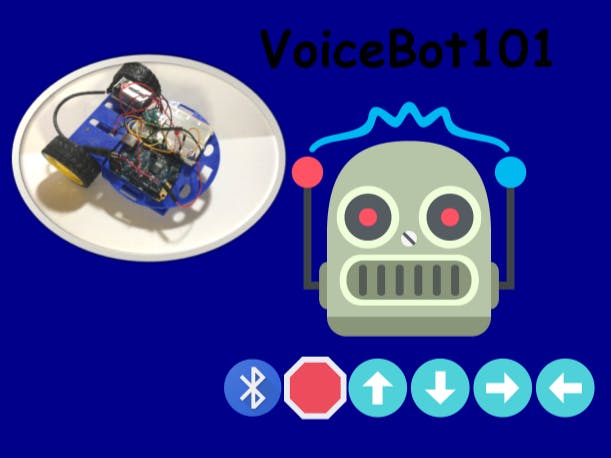
The interface page is specified in the html.index allows you to click on icons to move the robot around in addition to being able to utilize voice commands. This is important due to a bit of a latency in response to the voice commands. If the robot is heading for a a fall, and it takes some time to responds to the command "halt!", you can always just click on the stop icon. I used emojis from emojione.com to provide a fun and stylized look to the interface.
The annyang voice recognition library is easy to use and well documented. I won't go into details her. Reading the annyang docs, reading the code for this project and my prior project linked above will teach your more than a summary here. "Don't repeat yourself", as they say . . .
Enjoy!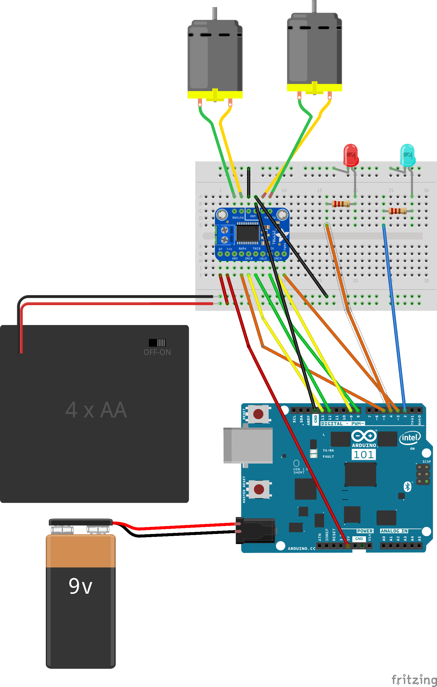


_t9PF3orMPd.png?auto=compress%2Cformat&w=40&h=40&fit=fillmax&bg=fff&dpr=2)


_3u05Tpwasz.png?auto=compress%2Cformat&w=40&h=40&fit=fillmax&bg=fff&dpr=2)


Comments