

_lveJouoMAu.png?auto=compress%2Cformat&w=900&h=675&fit=min)
Hardware components | ||||||
_baVEVgguW1.jpg?auto=compress%2Cformat&w=48&h=48&fit=fill&bg=ffffff) |
| × | 1 | |||
| × | 1 | ||||
 |
| × | 1 | |||
Software apps and online services | ||||||
 |
| |||||
| ||||||
| ||||||
| ||||||
Hand tools and fabrication machines | ||||||
 |
| |||||
 |
| |||||
When I finished working on my project, Voronoi101: Light Your Lamp, I decided I would eventually design and print a suitable enclosure for the Arduino 101 running it. The original project was designed for the adafruit BLE feather product, which has a smaller footprint than the Arduino 101. Like many future project ideas, it remained just an idea, until I came across a video on Chuck Hellebuyck’s 3D Printing show on YouTube. He had been inspired to 3D print an Edison style light bulb after a trip to a museum. The video includes a bit of history about Edison’s light bulbs and a neat light bulb experiment to try. It is well worth watching. I admired the form and beauty of the print and I had all the inspiration I needed to redo my project with a brand new enclosure, and more. Thanks Chuck!
For this project I’ll again use an Arduino 101 connected to a neopixel ring to light-up the light bulb. The major changes won’t be limited to the bulb/lamp and enclosure. I’ll add some special effects utilizing the CureTimerOne library. I’ll also design a browser based UI that takes advantage of the Web Bluetooth API to control everything.
So it's almost is an entirely new project and your time reading through this description will be well worth it!
The SoftwareLike many embedded and connected projects we can break the software into roughly two parts:
- A sketch running on our embedded Arduino 101
- The code that allows wireless interaction with it
The are many, many ways to write the second part. For this project, I used the Web Bluetooth API. This API will allows you to use HTML/Javascript/CSS to create a web page as the UI to interact with the light bulb. In my prior lamp project, I used the Evothings platform which is another excellent way to go. The Web Bluetooth API is a part of a broader effort known as "The Physical Web". I won't go into detail here on it, but it is similar to IoT and you can find much more about it on the the regular web! :)
The SketchThis will not be an exhaustive, line-by-line description of the sketch. Only the highlights of the code will be covered. The entire sketch is up on the project’s Github repository for you to read over.
The two main highlights in the sketch are the parts that deal with BLE connectivity and the parts creating the special light effects using CurieTimerOne.
BLE connectivity is established through the CurieBLE library. This is a library that is standard to the Arduino 101 and provides a convenient API for accessing the Arduino 101’s on board BLE capability.
Before diving into the specifics of the BLE code, let’s define what we want our light bulb service to do. An on/off switch is pretty obvious. It seems as if controlling the color of lights is pretty hot in the IoT world right now and using neopixels allows for precise color control. So a way to choose the color of the light would also be useful. The ability to adjust the brightness of the lamp would also be nice to have. Using various timing mechanisms, we could also provide some special effects for the light bulb. So how does this translate to BLE?
The on/off switch and the special effects could be handled with a single BLE characteristic declaring a variable of the BLEUnsignedCharCharacteristic type. This type can handle value from 0 to 255. So if we code this correctly, we can specify 255 unique special effects in addition to the on/off function. This is also purely a one way communication from the UI to the embedded Arduino 101 so we can advertise this with the keyword, BLEWrite when we declare this characteristic.
BLEUnsignedCharCharacteristic switchCharacteristic("917649A1-D98E-11E5-9EEC-0002A5D5C51B", BLEWrite);
To control the color of the light bulb, we will need to send a set of 3 values for the R, G and B components of the desired color. For this function, we will assume that each neopixel will take on the same 3 RGB values. This means that we need a characteristic of the BLECharacteristic type that allows us to transmit 3 bytes. These 3 bytes correspond to the R, G and B color component values from 0 to 255. Another characteristic of the BLEUnsignedCharCharacteristic type can be used to control the brightness of our lamp sending a value of 0 to 255.
BLEUnsignedCharCharacteristic brightnessCharacteristic("917649A2-D98E-11E5-9EEC-0002A5D5C51B", BLEWrite);
BLECharacteristic colorCharacteristic("917649A3-D98E-11E5-9EEC-0002A5D5C51B", BLEWrite,3);
In all these cases, values are written to the device from our UI, so we need only specify these with the BLEWrite keyword in their respective declarations. The entire service is specified in the code below:
/**
* Setup our BLE service and characteristics here
*/
BLEPeripheral blePeripheral;       // BLE Peripheral Device (the board you're programming)
BLEService lampService("917649A0-D98E-11E5-9EEC-0002A5D5C51B"); // Custom UUID
BLEUnsignedCharCharacteristic switchCharacteristic("917649A1-D98E-11E5-9EEC-0002A5D5C51B", BLEWrite);
BLEUnsignedCharCharacteristic brightnessCharacteristic("917649A2-D98E-11E5-9EEC-0002A5D5C51B", BLEWrite);
BLECharacteristic colorCharacteristic("917649A3-D98E-11E5-9EEC-0002A5D5C51B", BLEWrite,3);
BLEDescriptor lampDescriptor("2902", "ble");
Note the integer parameter 3 in the declaration of the color characteristic. This is how the 3 bytes are specified in the declaration.
The BLE service and all the service's characteristics have uuid’s. These will be needed when we create the UI code to run in our browser. They will allow the specific connections to be made from our browser to the service and allow our UI to send values to the characteristics in our service. There are standard uuid that are approved by the Bluetooth SIG. For custom services, such as this one, you create your own. There are numerous online tools to do this.
For the special effects, timing is everything and there are many paths to achieving the necessary timing to create these effects. The most common and straightforward method would be to utilize the delay() function from the standard Arduino IDE library of functions. The main drawback to this approach is that anytime the delay() function is called, all processor activity comes to a halt for the delay time. When BLE characteristics could be written to at any time, this could cause a lack of response to characteristic changes.
Another approach, uses an object oriented programming style and update functions in the loop() function of the sketch to provide the necessary timing. This approach was fully described in a set of tutorials by Bill Earl from adafruit. You can look at my Blinking LED project for another example of this approach.
A third approach is to use the timers provided by the Curie chip itself. In this case, we can use the CurieTimerOne library to do this. For this project, we will only have one special effect running on one neopixel ring at a time, so it is very straightforward to use the CurieTimerOne to meet our needs.
The easiest way to see how to use CurieTimerOne is the “blink” special effect which causes all the neopixels to turn on and off at a certain rate.
First we will define the blink functionality as an interrupt service routine(ISR). An ISR is simply a function that is called whenever an interrupt is generated. In response to an interrupt, the microcontroller will stop whatever it is doing and put a bookmark in that place. It will then execute the code within the ISR. When it is done with the ISR, it turns back to that bookmark and begins executing the code from where it left off.
In our case the interrupt is always the timer going off.
Here is the blink ISR:
void blinkISR()
{
   lampState.flip = !lampState.flip;
    if (lampState.flip)
    {
       for (int i = 0; i<light.numPixels(); i++)
       {
         light.setPixelColor(i, light.Color(lampState.green,lampState.red,lampState.blue));
       }
    }
   else
   {
     blank();
   }
   light.show();
}
In our code, we set up a state machine for our light bulb. For the purposes of this project, the state machine is simply a set of variables that keeps track of the what the lamp is doing or what state the lamp is in.
For instance in the code above, we have the lampState.flip variable being toggled which represents an on/off blink. When true, we turn all the neoxpixels in the ring to the current RGB color state of the lamp with the lampState.green, lampState.red and lampState.blue state variables. These hold the current RGB values as integer values from 0 to 255.
The full state machine is shown here:
struct LampStateStructure
{
 boolean lampOn;
 int brightness;
 int green;
 int red;
 int blue;
 boolean flip;
 int currentPixel;
 uint16_t colorIncrement;
};
As you can see it is basically just a list of variables wrapped in a C struct. Fancy name, no big deal.
The blank() function is defined in our sketch. It simply turns each of the neopixels in the ring off.
This is all a bit more complicated than what you would want in a standard ISR. Since the microcontroller is stoping what it was doing, it is wise to minimize the amount of code in an ISR. But it works and we're going with it. :)
With the blink ISR defined, we now need to connect this to the CurieTimerOne (remember our interrupt will be the expiration of a certain interval of time). For this project, we want the special effects to be called over BLE. We chose to use the switchCharacteristic to not only turn the light on and off, but also to control each of the special effects. As BLE characteristic changes can come asynchronously, we define a function to be called whenever there is a change of the switchCharacteristic. In this function we use a switch/case statement. You can expand this to account for any of the 256 potential switchCharacteristic values.
The switchCharacteristic value of 1 is the blink function. When a 1 is written to the switch characteristic, it gets fed into the switch/case statement of the switchCharacterisiticWritten() function.
First we stop CurieTimerOne. We have no idea what is going on at this point with the timer, so we bring it to a stop and then start it up again with an interval of 0.1 sec(100000 microsecords) and set it to call the blink ISR, simple!
void switchCharacteristicWritten(BLECentral& central, BLECharacteristic& characteristic)
{
 /**
  * We will use a switch/case statement here so that we can expand the functionality of the app
  * in the future; This will allow us to accept values up to 255 on the switch characteristic
  * and not permanently tie the characteritis to just turning the lamp on/off;
  */
  int switchValue = switchCharacteristic.value();
  Serial.print("Switch Value: "); Serial.println(switchValue);
  switch(switchValue)
  {
  ...
     case 1:
        CurieTimerOne.stop();
        CurieTimerOne.start(100000, &blinkISR);
       break;
  ...
You can read through the rest of the code to see how the other effects are implemented.
The WebpageIt should be noted that the Web Bluetooth API is still in a developmental stage and has very specific restrictions and limits around its use. You can can review these here: https://github.com/WebBluetoothCG/web-bluetooth/blob/gh-pages/implementation-status.md
This project will work on and has been tested on a chromebook, running the chrome web browser with the chrome webbluetooth experimental flag enabled. After consulting the capabilities in the lists above, you can test it out and let me know what works for you!
If you set up the Arduino 101 circuit as shown below and upload the sketch for this project, simply logging onto the BLElectric Light 101 website hosted in Github pages will allow you to interact with the light bulb right away. You will neither have to do any more coding, nor learn any more about the Web Bluetooth API. I suspect, however, that that’s not really why you are here reading about this on Hackster, is it? So the following description highlights how you would go about doing something like this on your own. This is meant to supplement, but not replace all the great tutorials available to you online. The best place to start is at the main author's , Francois Beaufort, post or at the Web Bluetooth CG Github page.
In order to use the Web Bluetooth API, we need a way to serve up a webpage with HTTPS. This is easily done through Github Pages. This requires a Github account and following the instructions at that page. This is a very convenient way to not only serve up your code, but also document and share your project code and other project files with the world. If you haven't gotten into Github yet, I strongly recommend doing it. It is clearly the way Makers, not just professionals, are sharing their work! Wayne Gretzky is famous for saying "skate to where the puck is going. . .", the Maker puck is going all the way to Github!
The beginning of your understanding in how make a webpage that uses the Web Bluetooth API to interact with your embedded project is to understand the file structure of one that works.
A note of caution here, I spent a long time trying to use the Web Bluetooth API at first, not because it is complicated, but because the first time I encountered it was through code written in the angular.js framework. I found myself absorbed with trying to learn learn angular.js and going nowhere fast with both my coding and my projects. So I dumped that apporach and took a bare bones approach adapted from the links I provided above.
The file structure of our project will include an index.html file. This is homepage of the project and will include the basic outline of the webpage. As the file extension indicates, this file will be written with HTML. This means that you have all the power and years of refinement and development of UI design using HTML to access when designing your interface!
Within our file structure, you will see a folder named css. This directory contains the css.style file with contains all the styling and detailing of the elements specific in our index.html file. I won’t go into any details here, but give some advice on CSS: If you want to do something with CSS, there is probably a blog post, tutorial or post somewhere on the very thing you want to do. Just google it, read, try and learn!
The images directory is a convenient place to store all the image files you will use for your webpage. It is not required but a really good idea to have one.
The Javascript FilesThere will are two javascript files, blelectricLight.js and app.js.
The role of blelectricLight.js is to represent the entire BLE service. This will include all the uuids that specify the BLE service and characteristics. The constructor() function builds up our service from the given uuids. It also gives a name to our service. We will see this name when we attempt to connect to the BLE device. It also caches all the uuids at the time of connecting for access later, and defines read and write functions. The constructor is called at the very bottom of the file. This var name will be used in the app.js file.
The role of app.js is to connect the actions of our embedded device with ui elements of the index.html file. As you can see from reading the code, every action we can perform in the index.html finds a representation in the code here. For instance, if we click on the light bulb emoji on the UI, we cause the following code to be executed from index.html:
<img onclick="sendCommand(0)" width="100" height="100" src="./images/onoff.png">
The onclick keyword in the <img> tag tells the browser to call the sendCommand() function in our app.js file with a parameter of 0.
function sendCommand(value)
{
  switch(value)
  {
     case(0):
        blelectriclight._writeCharacteristic(blelectriclight.switchUUID, new Uint8Array([0]));
        break;
    ...
  }
};
Now in the app.js file, sendCommand() is executed. We see the that our old friend switch/case is here to select an action to perform based on the value passed into the sendCommand() function, which in this case is 0. The sendCommand( ) function then uses the blelectriclight object created in the blelectricLight.js file to call the _writeCharacteristic() function. This function takes the switchUUID of our embedded device and writes a 0 to it. Now you can see how app.js connects the elements in the index.html file with the actions of our embedded device with the BLE service defined in blelelectricLight.js!
There are many ways to construct a webpage and many different frameworks that you could explore, but this bare bones approach will get you started experimenting and understanding how all the elements of a HTML/Javascript/CSS web page work together with the Web Bluetooth API to interact with your embedded device.
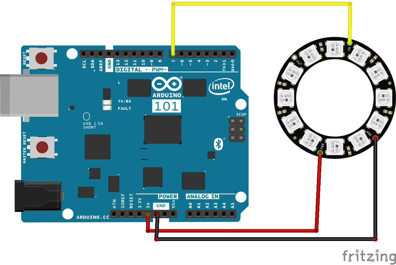
The Arduino 101 CircuitThe electronics for this project are quite easy to put to together. The Arduino 101 comes with onboard BLE capability, so no special hardware or wiring is required for this. The neopixel ring can be powered from the board. Make a connection between the power and ground on the ring to the 5V and ground on the Arduino 101. For this project I have selected pin 7 on the Arduino 101 to send commands or data to the neopixel ring, so connect a wire to this pin on the board. Then simply plug the power supply into the jack on the board and you are ready to go.
The 3D printThe 3D print consists of 5 different pieces. The light bulb, the socket, the base ring, a cap for the base and a support structure for the neoxpixel ring. All these are available as .stl files for you.
I have printed the light bulb with 3 types of filament: Clear ABS, PCTPE and Blue tGlase. Both the clear ABS and PCPTE look the best to me. What do you think? If you made one, what did you print it with?
Although Chuck Hellebuyck recommends and demonstrates printing the light bulb with a support structure, I did not. Actually, my first print was done with support material, but removing it was difficult and caused some damage to the structure. So I tried without itand was happily surprised. The print came out nearly perfect with all 3 filament types with no supports at all! I believe the incremental circumferential print creates a natural cantilever effect from layer to layer thereby negating the need for support material.
All prints were made with a lulzbot mini, using Cura with the recommended or standard settings for the different filaments types. No special tweeks here other than using a glue stick on the board.
Very Important: In order to fit the neopixel ring, you will need to scale up the X,Y and Z to 1.24. Slightly smaller prints will work, but will not create a snug fit.
Once printed, the pieces snap together as below:
A fun project from Print to UI! If you make one, let me know!


_t9PF3orMPd.png?auto=compress%2Cformat&w=40&h=40&fit=fillmax&bg=fff&dpr=2)


Comments