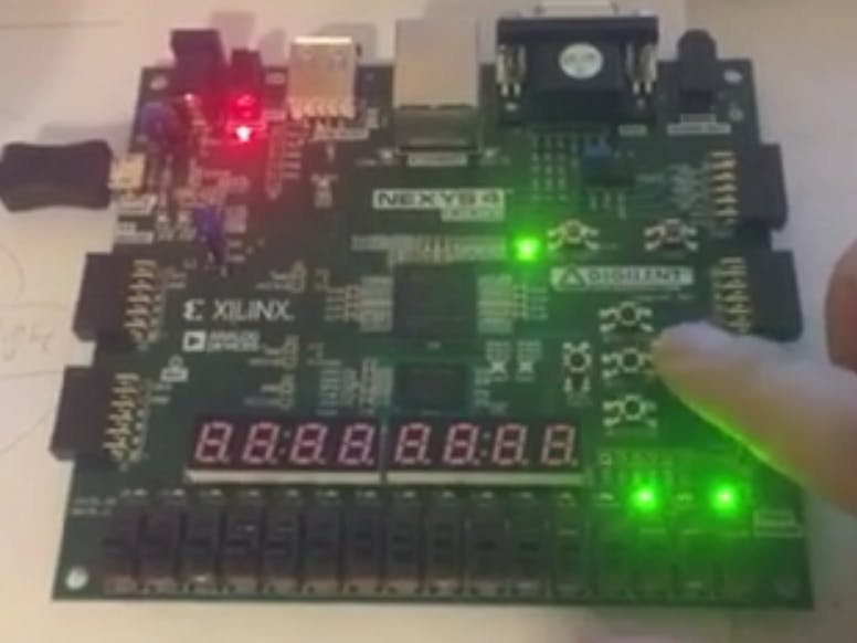
Use VHDL to implement a simple digital combination lock state machine that can be used to lock and unlock the locker. This combination lock state machine has 4 “key” input push button on the Nexys 4 FPGA board. In additional to the 4 input keys, there is also a 5th input push button in center to “activates” the lock with one output LEDs on board to indicates whether the lock is locked or unlocked. Initially, the lock is on the locked state.
To unlock the lock, the 4 push button inputs must be push in the "correct" order; in here we designed the order as push “Button Up(BTNU)” first, push “Button Right (BTNR)” second, after that push “Button Down (BTND)”, then push “Button Left (BTNL)” and finally push activate input “Button Center (BTNC)” to unlocked the locker. If the keys are push in wrong order, then the lock will stay in the lock state until correct order is asserted. At any time during unlocked state, press any 4 of input keys will cause lock go back to "locked" state again.
Video of how it works:


Comments