



Disclosure: I work for ERDILRF (Chengdu), the manufacturer of these modules. Every frame, baud rate and unit here is transcribed from the manufacturer manuals and implemented in an MIT-licensed driver. No bench measurements are published in this project; see "What is not verified" at the end.
Things used in this projectHardware
- One ERDI 905 nm laser rangefinder module (worked example: LRF3000A1)
- Arduino board with a spare hardware UART (Mega, ESP32, etc.), or
- Raspberry Pi + USB-TTL adapter, or
- A ROS 2 machine + USB-TTL adapter
- Jumper wires and a power supply matching your exact model
Software
ErdiLRFArduino library (Library Manager / PlatformIOerdi-tech/ErdiLRF)erdi_lrfPython package (v0.1.0 wheel)erdi_lrf_ros2package- Any serial terminal with hex view
A UART rangefinder looks like the easiest sensor on the bill of materials. Four wires, a baud rate, done.
Then you power it up and the terminal stays silent. Or worse, you get a clean stream of distances that are exactly ten times wrong.
In a drone's altitude hold or a robot's obstacle check, a silent error like that is the dangerous kind. Nothing crashes. The number is just wrong.
When a first integration goes sideways, the cause usually isn't the wiring. It's protocol detail. And our own 905 nm catalogue has two protocol families with different framing, different checksums and different units. So the useful thing to build wasn't another example sketch. It was one driver that encodes all of those rules per model and refuses to guess where the manuals are ambiguous.
WhatThe driver covers both families:
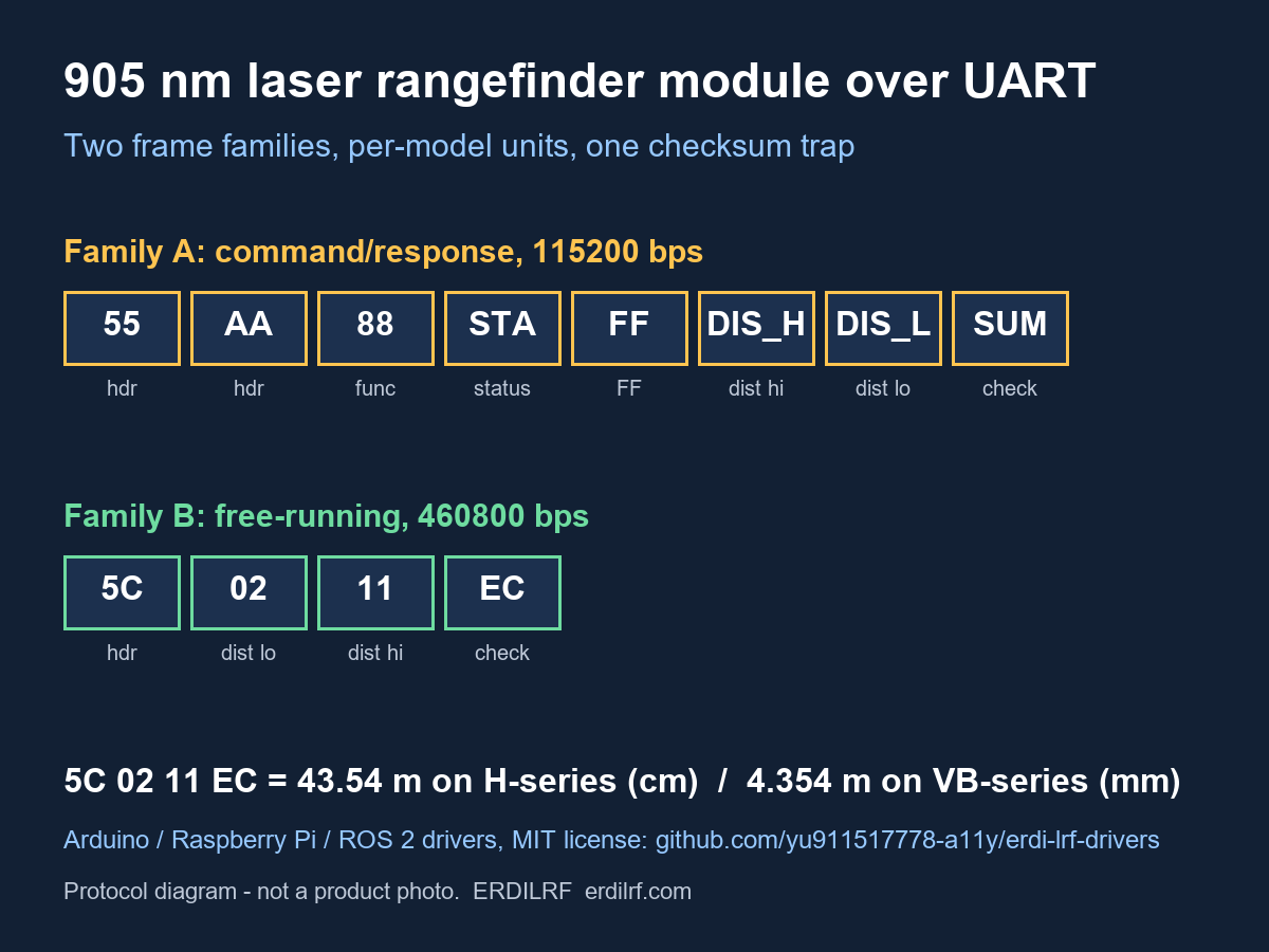
Family A: 8-byte 55 AA command/response, 115200 bps default.LR1000E2/E4, LR1200E2/E4, LR1500E2/E4, LR2000E2/E4, LRF1200A1, LRF3000A1, SPD1200N0/N2/N4, SPD1200D03. SPD1200D03 is an exception: its source manual has conflicting baud statements, so confirm the delivered setting; the driver requires an explicit baud.
Family B: free-running 5C frames, 460800 bps default (adjustable), 8 data bits, 1 stop bit, no parity, little-endian.LRF50H/100H/200H/300H/600H/1500H, LRF22VB, LRF50VB.
It ships as three front-ends over the same rules: an Arduino library, a Python package with a CLI, and a ROS 2 node publishing sensor_msgs/Range.
1. Asymmetric checksums (family A).Request 55 AA 88 FF FF FF FF 84, reply 55 AA 88 STA FF DIS_H DIS_L SUM.
- Transmit checksum: low 8 bits of Function + D1..D4
- Reply checksum: low 8 bits of 0x55 + 0xAA + Function + D1..D4
They differ by exactly 0xFF. Use the transmit formula on replies and you're off by one on almost every frame.
Worked example (constructed, not captured from hardware): 55 AA 88 01 FF 04 D2 5D sums to 0x35D, low byte 0x5D. STA = 1 means success. Distance 0x04D2 = 1234 counts. The manual says output is real value x 10, so that's 123.4 m.
2. Units per model (family B).Frame 5C dist_lo dist_hi check. The check is the bitwise inverse of the sum of the middle bytes: for 5C 02 11 EC, ~(0x02 + 0x11) = 0xEC.
That same frame is 43.54 m on an H-series module (centimetres) and 4.354 m on LRF22VB/LRF50VB (millimetres). The driver requires a model name. It never infers units from the family.
LRF1500H is the one 5-byte frame (3-byte distance). Its manual's example frame fails its own checksum formula, and the driver keeps that discrepancy flagged rather than silently patched.
3. Manuals that disagree with themselves.
- SPD1200D03: protocol section says 115200 bps, technical table says 15200/9600. The driver demands an explicit baud and returns no metric distance.
- LRF1200A1 / LRF3000A1: continuous ranging is requested with 0x89 but the recorded reply uses 0x88, and the manual declines to authorise a reply parser. Single-shot is unaffected; continuous parsing stays off until manually confirmed.
- LRF50VB: the printed serial-number request fails the manual's own checksum function.
Supply voltage and UART signal level are separate specs. LRF3000A1, 6-pin connector A1002WV-S-6P, per its manual:
- 1 — GND — Ground
- 2 — Power — 3.3-5 V DC
- 3 — NC — Reserved
- 4 — TTL_TXD — Module transmit, 3.3 V TTL
- 5 — TTL_RXD — Module receive, 3.3 V TTL
- 6 — Enable — Power ON at low level
Module TX to host RX, module RX to host TX, common ground. Other models differ a lot: LRF50H takes 9-36 V, LRF22VB takes 3.0-3.6 V. If a manual doesn't state the signal level, get it confirmed in writing first.
The logical connection map below is for LRF3000A1. It does not show connector viewing direction or a board-specific pinout.
Step 2: Arduino#include <ErdiLRF.h>
ErdiLRF lrf(Serial1, ERDI_LRF3000A1);
void setup() {
Serial.begin(115200);
Serial1.begin(erdiDefaultBaud(ERDI_LRF3000A1)); // 115200 for family A, 460800 for family B
}
void loop() {
ErdiMeasurement m;
if (lrf.measure(&m) == ERDI_OK) Serial.println(m.metres, 3);
delay(500);
}SoftwareSerial on an Uno can't reach 460800 bps. Use a hardware UART for family B, or set the module to a lower documented rate first.
Step 3: Raspberry Pipip install https://github.com/ErdiTech/erdi-lrf-drivers/releases/download/v0.1.0/erdi_lrf-0.1.0-py3-none-any.whl
erdi-lrf --port /dev/ttyUSB0 --model LRF3000A1 measure
from erdi_lrf import ErdiLRF
with ErdiLRF("/dev/ttyUSB0", model="LRF3000A1") as lrf:
print(f"{lrf.measure().metres:.1f} m")
with ErdiLRF("/dev/ttyUSB0", model="LRF100H") as lrf:
for m in lrf.stream():
print(m.metres, "(out of range)" if m.out_of_range else "")The codecs are pure functions with no serial dependency, so you can unit-test them offline.
Step 4: ROS 2cp -r ros2/erdi_lrf_ros2 ~/ros2_ws/src/
cd ~/ros2_ws && colcon build --packages-select erdi_lrf_ros2
source install/setup.bash
ros2 run erdi_lrf_ros2 range_node --ros-args -p port:=/dev/ttyUSB0 -p model:=LRF3000A1 -p rate:=10.0 -p frame_id:=lrf_linkmin_range/max_range come from the model manual. field_of_view defaults to 0 because the protocol manuals carry no beam divergence; set it from your datasheet.
- No measurement results or performance claims are made here. Read the datasheet for your model.
- The ROS 2 node has been tested in software replay only, not against a live ROS 2 runtime with hardware.
- The driver tests are built from the frames printed in the manuals.
The most useful contributions are reports where a real unit disagrees with its manual. Those go straight into the model table. Issues and PRs are welcome on the repo.
Code and links- Driver repo (MIT): https://github.com/ErdiTech/erdi-lrf-drivers
- Arduino library: https://github.com/ErdiTech/ErdiLRF
- Technical note (DOI): https://doi.org/10.5281/zenodo.23297197
- Model catalogue: https://erdilrf.com/models/
Vendor disclosure: the author is affiliated with ERDI TECH LTD (ERDILRF). For samples, datasheets or protocol questions: https://erdilrf.com or [email protected].


Comments