

Hardware components | ||||||
 |
| × | 1 | |||
| × | 1 | ||||
| × | 1 | ||||
Software apps and online services | ||||||
| ||||||
| ||||||
| ||||||
Hand tools and fabrication machines | ||||||
 |
| |||||
In the industrial space, relays and contactors are controlled by a high voltage to switch an even higher voltage. My design will be able to characterize these devices that have an input control voltage up to 600VDC. I am not aware of any other self-contained device that has this functionality in the test space. This would replace manual testing and an automated system will reduce time, errors, and danger.
It's important to know the specifications of coil inside these devices so that any product that uses them can control them over their full design range. For instance, a typical 24VDC relay may actually turn on at 18VDC and not turn off until the voltage falls below 6VDC. An issue may be caused if there is a lot of capacitance on the input control line which could make it take longer than expected for the voltage connected to the coil to bleed off to 6V. This means that the relay may stay closed longer than expected which could damage any equipment connected to the output. Not only are the specifications of the coil important for the circuit design that controls it, but the coils may be characterized using this hardware at the factory. This could ensure they work correctly and faulty relays or contactors are not sent into the field.
Throughout testing, I have determined that I cannot meet all of the goals of the project. This project still serves a purpose and is functional. The rest of this post will explain the hardware, firmware, and testing performed on my designed project.
Video OverviewIt's Friday night. I have everything complete for the Powering the Future with Infineon contest. There's a few hours until submissions are due so I thought I had time to record a video of the operation. You'll see in the video that I explain the circuit and then power up the board to demonstrate it and disaster strikes. I had the alligator clip with +30VDC on it and touched something by accident and nearly welded it in place. I was looking through my phone's camera at the time so I didn't realize how close I was to the circuit board. The worst part is I wasn't even recording! Other than the short clip at the end, I don't have any other recordings of my project working. If I had more time, I'm sure I could troubleshoot the circuit or even assemble a new one. The FPGA development board powers up by itself so there's not many other components that could be damaged. I'm disappointed and sorry that there's no more video details of the project, but I think the rest of this post has a great deal of good information on my circuit. Enjoy!
HardwareThe hardware is comprised of several blocks. They are a power supply to go from 120VAC to +15V and +3.3V, a TinyFPGA BX FPGA development board for the control, UART header for feedback to PC, Infineon MOSFET and gate driver, discrete component voltage controlled oscillator, and various comparators for sensing and feedback.
Power Supply
I'm using a Recom RAC02-15SGA module to regulate the 120VAC input down to +15VDC. This +15V rail is used for the MOSFET driver for controlling the MOSFET and for the comparators and op-amps so they have more margin for measurements. Then the +15VDC is converted to +3.3VDC with another Recom module (this one is an R-78E3.3-0.5, which is basically a 7805 replacement).
This board is powered from 120VAC, so be careful with that portion of the circuit. You can also choose not to use the RAC02 module and instead input +15VDC into the output of that chip's footprint (pins 4 and 3) to power the circuit.
The external relay is powered from a DC supply connected to connector X2. I used a lab bench power supply to input 30VDC, but it should support any DC voltage you choose up to 600VDC (read the rest of the post for more detail).
FPGA
I'm using a TinyFPGA BX for the control. This nifty FPGA board is excellent for the project because it simplifies the board layout and firmware upload process. It's possible that this block could be replaced by a microcontroller, but I wanted an excuse to use an FPGA 😉. I also added a reset button to quickly get the FPGA into a known good state.
UART
I added a simple UART header with the pinout of a SparkFun Serial Basic Breakout (seems to be a common UART header pinout) for communication to a PC to display status messages. I have performed all testing with an Adafruit USB to TTL Serial Cable though. Although my code is strictly status messages from the FPGA, the hardware supports communication from the PC to the FPGA for other control.
Infineon MOSFET and GateDriver
I'm using an Infineon IPT60R028G7 MOSFET because of the low RDS(on) to minimize heat and the large VDS capabilities to test any type of coil. Although I've only tested switching up to a 50VDC voltage, all of the components in this switching path are rated to 600VDC. I'm using an Infineon 2EDN7424FXTMA1 as the gate driver since it has an easy to hand-solder package, is relatively inexpensive, and has all of the features I need for my board. I was really surprised at how easy this gate driver is to use. No calculations or other components necessary. Just plop it in the schematic and it works,
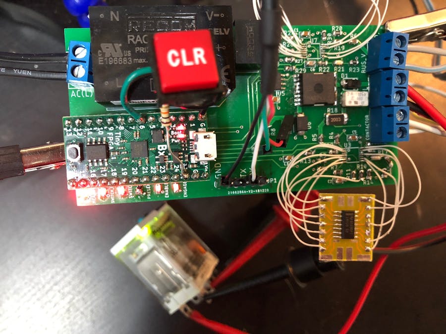
Hardware Corrections
As you can see in the above image, I had to do some rework on my produced PCB to test it. Most notably, I used incorrect footprints for two ICs. There were a few minor resistor placement errors but I found and corrected them. I also adjusted some footprints to make the soldering easier.
Design Cost
I had my boards produced at JLCPCB for $20 including rush shipping. I added a majority of the jellybean components from LCSC for another $20 and they shipped with the PCB. I had to buy the more complex chips from Mouser and they cost about $40. The TinyFPA is another $40. So for $120 all in, I have enough parts to make a few copies of this board.
FirmwareIntroduction
As previously mentioned, I used a TinyFPGA BX board for this project as an excuse to use an FPGA. I have experience working with FPGAs but I've never started my own project from scratch. I also used Verilog for this project while I've typically used VHDL in the past. My main firmware file is attached below.
Application
Following this guide, I was able to get the PC software apio up and running very quickly. It's unbelievable that the full process of designing the logic inside an FPGA is open source. I'm also very impressed with the USB bootloader on this chip and how it doesn't require an external programmer to get started working.
UART Module
I thought it would be nice to have some communication between the FPGA and a PC. I even had high hopes of designing a GUI to really control things. But you need to start somewhere and I started with the UART block. I searched online for some existing code because I didn't want to write this (seemingly common) firmware by myself. I didn't find many implementations of UART in firmware, but I did find this article on Hackaday which explained it nicely. This project is written in Verilog and it's the main reason I chose that language for this project. The actual UART block is found here and this is an example project that uses it.
Testing
Of course, I started to acclimate myself to this new build process by building a "blinky". Due to the parallel nature of FPGAs, I actually kept the blinky portion of the code in place so I could always look at the user LED and ensure that things are working correctly.
I've never done any simulations on FPGA designs, but I was having problems getting the UART to work so I wrote a test bench to get started. I used ModelSim since I already had it installed. Writing code and testing immediately with a test bench is a complete game changer. I was able to incrementally add steps to my code until I got the UART fully working. I even found a bug in the UART library along the way. I don't think I would've ever got this working without a test bench.
State Machine
One of the most frustrating parts for me is wrapping my head around the way an FPGA operates. I'm used to microcontrollers and how they operate line by line, so it took me a while to understand how to correctly format a Verilog program so it gave me desirable results. It turns out that designing all of my code inside a state machine (seen above) is exactly what I needed. Essentially each state happens inside one clock cycle so an operation can take place and then make a determination on which state to hit during the next clock cycle. Although the state machine shown above is not easy to understand, I'll try my best to explain what my code does below.
RESET State
FPGAs really need a reset state to ensure that all "variables" are set to what you expect. I went pretty far into my design without a reset state and I think I encountered lots of weird behavior because data wasn't what I expect. I also didn't have a reset button on my initial hardware, thus I added a big red "CLR" button to get everything into the right state.
INIT, STATE0-4 ("Relay Control")
The 6 states along the left side of the diagram are the main control of the inputs and outputs. They work like this:
INIT: Starts the process when the coil is presentSTATE0: Enables the MOSFET driverSTATE1: Controls the MOSFET gateSTATE2: Continues when it detects that the MOSFET has been switched onSTATE3: Continues when it detects that the relay output has been switched onSTATE4: A final state that will go to the INIT state when it detects that the relay has been disconnected.
As you can see from the diagram, some states will loop until a signal changes, while others only do one thing and then move on. It's important to make each state only do one thing so there is no timing errors or race conditions between signals. You can also see that most of these states jump to the LOAD_DATA state. This begins the UART transmission and will be explained next.
UART TX States
Before jumping to the LOAD_DATA state, I store the current state in a reg message. message is used for two things: 1) to ensure the right message is printed and 2) to know which state to jump to after the UART message. Here's the breakdown of each state:
LOAD_DATA: As mentioned, this stores a predefined message into memory based onmessageTRANSMIT: This puts a character from that message in memory onto the UART. The specific character is calculated fromcharptr, which is essentially a pointer which is incremented each loop. A signal is then set which triggers the UART to start transmitting.NEXTCHAR: This state incrementscharptrwhich was explained in the last state. It also resets the trigger signal from the last state so it can be reused later.WAIT: This state loops until the UART block responds that it has completely sent that last character. Because UART is a serial protocol, this takes a set amount of time (at 9600 baud, each character takes about 104 microseconds).COMPLETE: This state has two purposes. If we haven't reached the end of the message (charptris compared to the length of the message), we go back toLOAD_DATAand the next character is sent. If we did already send the last character, we use that dual-purpose regmessageto jump to the correct state (this is how theCOMPLETEblock in the state diagram photo knows where to go).
Here's a video of the full operation when the relay is connected:
I had to record in slow motion to see it at all. It appears instantaneous when looking at it.
Here's what shows up in the serial console:
I wrote in the elevator pitch that this board would determine the pull voltage (turn on) and drop out voltage (turn off) of a coil. I wrote a different version of firmware (inside the PWM branch) that is largely the same, but contains a PWM block and can control the MOSFET driver and thus the MOSFET with a PWM signal.
This code uses the same UART block and mostly the same state machine. The two main changes are:
- I removed
STATE2-- the MOSFET detection using the diode. Since the MOSFET is switching so fast, the diode never has time to saturate so the detection circuit never turns on. STATE4is changed to enable the PWM and then print the duty cycle.
Let me explain the PWM block. It has three variables, period, duty cycle, and position. The period is fixed in my design and is 100 decimal (100x 16Mhz clock cycles = 6-microsecond period). I chose this period because it makes the duty cycle calculation easy (a percent calculation of 100 is just the duty cycle). The duty cycle is the portion of the period where the gate driver is high. Lastly is the position which is incremented every clock cycle to determine when to turn on and off the gate driver.
STATE4 sets the duty cycle starting at 1 and then runs a full period of the PWM to determine if the relay was switched. If not, it will increase the duty cycle and try again on the next period. Once the MOSFET is on, the duty cycle is locked in place and the PWM block works in the background without direct control.
STATE4 calls LOAD_DATA just like my other code, but this time the message has changed. As shown in the image above, the character sent over UART corresponds to the duty cycle. It's possible to write code like this in C or Python but I was surprised that it works the same here.
Now the unfortunate part... I found out that the MOSFET always "turns on" at about 80% duty cycle. This is regardless of the voltage feeding it or the voltage rating of the coil connected. I'm honestly not entirely sure why this is but it ruins my idea of using PWM to control the voltage that is sent to the coil.
I planned to design the PWM block so I could increase the duty cycle until the coil turns on the relay and then reduce the duty cycle until the coil turns off the relay. I didn't write this code because it's always going to turn on and off at the same position.
If anyone has any ideas of why this is happening or what I can change to make it work as I described, I would appreciate it greatly.
VCO
I haven't mentioned much about the Voltage Controlled Oscillator. I have tested it and it works. As in, I can input a higher or lower voltage and the frequency out goes up or down following the simulation. I did not write any firmware to measure this because of the constant duty cycle issue described above. My idea was to make a new state after the relay is enabled that would read the frequency and possibly convert that to a voltage and print it over UART. Since the voltage is always the same, I didn't write this part of the firmware yet, but I am interested in writing it in the future for the challenge.
Although the outcome of the project was not exactly what I expected, I still think it's a useful tool for an industrial test lab. Instead of this board controlling the voltage to the coil, an external, adjustable power supply could be used. This board could then turn on the MOSFET and see if the voltage was enough to turn on the relay's output. If not, adjust the voltage and try again. This could all be automated and this makes it safer than a person having to be close and adjust voltages up to 600VDC.
I learned a ton about FPGAs and their logic. For projects that can be designed with a state machine, I think they're better suited than a microcontroller. Simulation tools for HDL make designing projects with those languages very quick and I had a great time working through the design of the logic of this project.

_t9PF3orMPd.png?auto=compress%2Cformat&w=40&h=40&fit=fillmax&bg=fff&dpr=2)


Comments