

Hardware components | ||||||
 |
| × | 1 | |||
Software apps and online services | ||||||
| ||||||
| ||||||
Sometimes you want to make a custom IP core. It could be a core that interfaces with cameras, audio codecs, or even a display. Designing, writing, and debugging that core is only part of the process. The next step is to put that core on an FPGA. After you put that core on an FPGA how do you interface with that core? Do you use buttons or switches to configure your core? What if you want to do something more elaborate like reading and writing audio or video data. How do you do that?
AXI is the answer. If you learn the AXI bus you will never have to spend your time figuring out how to stimulate your core with buttons or switches. You won't need to design a custom UART interface to talk to your core. You can display video on a VGA or even an HD monitor.
As an example of what can be done with an AXI core, the following is a video of a Pynq board with a custom PMOD LCD and an LCD driver core that uses two different AXI interfaces, an AXI Lite Slave interface to configure the core and an AXI Stream interface that receives video frames and converts the video data to compatible signals for the LCD.
In this series, I'll discuss how to use the AXI protocol with a set of tools to simplify the process of writing, simulating, converting that core to a Vivado compatible block, and finally talking with that core using a Jupyter Python3 notebook.
By the end, you will have all the tools you need to design, simulate, build and interact with a core of your own. Although all of these posts create bitstreams for the Pynq Z2 the cores generated are generic for any FPGAs.
Initially, I wrote a single post for the project but it was too big, so I broke down the project into five parts:
- Part 1: Introduction, blitz our way to a custom core you can talk with using Jupyter notebook on a Pynq board. This will also serve as the foundation of future parts. (You are here)
- Part 2: Adding new features to our core and using Cocotb to simulate and debug our core.
- Part 3: Manually build the core within the Vivado IP core generator.
- Part 4: Working with AXI Streams to read and write raw data.
- Part 5: Writing video frames using AXI Streams
For the most part, the two interfaces, AXI Lite and AXI Stream are the protocols used in cores. At first glance, the AXI interface may be intimidating, especially when compared to something like the Wishbone bus. Even the 'Lite' version has 5 channels of communication! But when broken down the protocol is surprisingly simple.
At a High LevelThe steps we will do in this post are:
- Install all the necessary tools, a one time step needed to set up an environment
- Run the script to generate a new IP core
- Generate a Xilinx Vivado IP core using a script
- Incorporate that component into a Vivado design
- Upload the 'bit' and 'hwh' file
- Use Jupyter notebook to exercise the core
Note: The following instructions are for Ubuntu. This can be accomplished with a standalone Ubuntu desktop/laptop, a virtual box, or even Window Subsystem for Linux (WSL). If using WSL I recommend using MobaXterm the free version will work fine and it has an XServer to run GTKWave.
If not done already Install the Pynq Z2 Board File
Install the necessary packages
sudo apt install build-essential gtkwave iverilogInstall the necessary Python 3 modules
pip3 install cocotb cocotb-bus cocotbext-axi pytestClone the repo into your directory of choice and move it into the repo
https://github.com/cospan/ip-cores.git
cd ip-coresCreate a new IP Core
Within the IP-core repo run the 'new-ip-core' script giving the script a name for your core, for the name 'demo_part1' is used.
./scripts/new-ip-core.sh demo_part1Move into the created directory
cd cores/demo_part1At this point, you can either edit/debug your core (more on this in part 2), manually build an IP core (Part 3). For this first version we won't modify the core we will just create this core and interact with it.
If not done already source the 'settings64.sh' or whatever script is appropriate for your system to set up the Xilinx tools. On my system it looks like this:
source ~/software/Xilinx/Vivado/2019.2/settings64.shThis will add the Xilinx tools to the current terminal settings and allow you to run Xilinx tools such as Vivado.
Run the following command:
make xilinx_ip_no_guiThis will go through the entire process of making a core. I'll go into more detail later. We will also do this whole process manually in Part 3
Insert the core into a Vivado ProjectNow that the core is ready we need to incorporate it into a Vivado Project. To simplify this process I've attached a zip file called 'Barebones Pynq Z2 Design'. It is the barest Pynq Z2 Project possible.
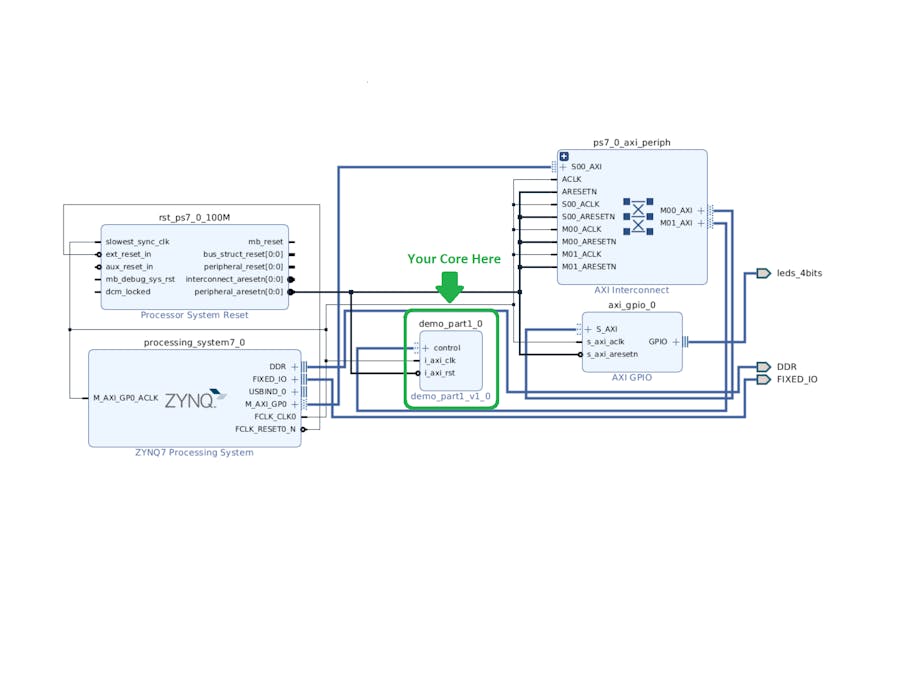
If you are not using a 2019.2 version of Vivado you will be asked to 'Automatically upgrade to the current version', say 'OK'. After opening it may warn you about the IP upgrading to the current release, select 'Report IP Status' and follow through with any changes required (most likely none). Open the block diagram and you should see this:
To show what happens when you add an existing core, open up the 'Board' tab on the left and drag in the '4 LEDs' into your block diagram.
Say 'OK' to any dialog boxes. Then on the top of the block diagram in the green bar select 'Run Connection Automation' and accept the default options, the output should look like this:
You can build this entire project upload the appropriate files to your Pynq board and flash some LEDs but before we do that we can add our custom IP.
To add our custom IP select 'Settings' in the 'Flow Navigator' under the 'Project Manager'
Within the 'Settings Dialog' select 'Repository' and then the '+', navigate to the base of the 'ip-core' directory you created earlier. Here is a visual reference:
Hit 'select' and you should see a dialog, press 'OK' and now a new path will be added to your repo, you can now add the custom IP core.
Note: The process of adding a new repository only needs to be done one time but you may need to go back in here and hit 'Refresh All' for Vivado to find the new IP cores you created.
Hit 'OK' to exit
Click 'IP Catalog', select your new 'demo_part1' core, and select 'Add IP to Block Diagram'
Similar to the LEDs added before select 'Run Connection Automation' at the top to connect everything.
Select 'Generate Bitstream' in the 'Flow Navigator' and let it create a bit file
On the Pynq board
For the most part, we will be using the Jupyter notebooks but in order to clone the git repo, we need to use the command line, to do this go into Jupyter and open up a terminal from the 'New' menu on the right.
Move into the 'juptyer_notebook' directory
cd jupyter_notebookI created a git repo to augment the Pynq notebooks, clone it into a 'Projects' directory
git clone https://github.com/cospan/pynq-projects.git ProjectsMove into the repo
cd ProjectsWe're done with the terminal, back to the web interface.
A directory called 'Projects/demo_part1' is now available, Using the Jupyter notebook you will need to copy some files from your Vivado project into the 'data' folder of that 'demo_part1' directory. Specifically the 'bit' file and the 'hwh' file from the Vivado project. The 'bit' file is the image to download onto the FPGA portion of the Zynq chip and the 'hwh' is a file describing the image.
Move into the 'data' folder for 'demo_part1' within the Jupyter notebook
Projects/demo-par1/dataFor a visual reference, you can see the image below
Now we can upload the files using the Jupyter notebook interface.
You will need to navigate the location of the Vivado project that was created above, for reference I call this location <vivado project base>/<project name> so if I built the project in my home directory
<vivado project base> = ~/pynq_z2_barebonesThe project name would be
<project name> = pynq_z2_barebonesUsing this, the bit file can be found here:
<vivado project base>/<project name>.runs/impl_1/system_wrapper.bitThe hwh file can be found here:
<vivado project base>/<project name>.srcs/sources_1/bd/system/hw_handoff/system.hwhThere is a caveat here, the files need to have the same file name and 'system_wrapper' != 'system' so you will need to change 'system.hwh' to 'system_wrapper.hwh' but this can be done easily within the Jupyter notebook.
Once this is done and the directory looks like it does in the above image move back to the 'Projects/demo_part1' directory and open up the 'demo_part1.ipnyb'.
Run the first block to download the bit file, run the second block to exercise the core.
In this first part, we discussed how AXI can be used to tap into Xilinx's existing AXI infrastructure. We generated a simple IP core, put it onto a Pynq Z2 board, and interacted with it. In Part 2 we are going to modify this core. We will use Cocotb to simulate it. In the process of simulating and debugging our core, we will need to write a Python driver. A very nice benefit of using Python to write this simulation driver is that it will be almost identical to the driver we write to talk to the actual core. In Part 3 we will manually build the IP core instead of using the command line script. This will introduce you to how we specify what signals belong to the AXI bus. In Part 4 we will add an AXI Stream interface to read and write raw data. Finally, in Part 5 we will generate video and write that video out to an HDMI monitor.
Appendix
This article is long enough, after some consideration I moved the following sections here for anyone interested.
Appendix A: The AXI protocolAXI Lite Bus
The AXI protocol describes multiple interfaces including AXI Master, AXI Slave, AXI Lite Master, AXI Lite Slave, Interconnects, AXI Stream, etc... There are plenty of resources available including the following:
For this article, I'll focus on the AXI Lite bus, which has 5 channels of communication, at a high level here are what all the channels do.
- Write Control Channel: Tell the bus that we want to write 1 piece of 32-bit data as well as the address to write to.
- Read Control Channel: Tell the bus that we want to read 1 piece of 32-bit data as well as the address to read from.
- Write Data Channel: The data we want to send to the core.
- Read Data Channel: The data we want to receive from the core.
- Write Response Channel: The status of a write transaction.
Why 5 channels!?? This is to keep the AXI Lite compatible with the normal AXI. There are roughly three differences between the AXI and AXI Lite protocols.
- AXI Lite can only send/receive data with a word size of 32-bits while AXI can send data in the size of 32, 64, 128, 512, or 1024 bits.
- AXI Lite can only send/receive 1 word of data in a single transaction while AXI can stream up to 256 words in a single transaction.
- AXI Lite allows only 1 transaction at a time while AXI, because of its separate read/write control channels, can prepare the core to receive/send nearly a continuous stream of data.
At first AXI Lite may seem limited in scope but it is very useful for configuring a core by reading and writing individual registers.
What about the AXI Streams? Well, I'm glad I asked myself!
AXI Read/Write Stream Protocol
AXI Streams are simply the 'Write Data Channel' or 'Read Data Channel' portion of the AXI protocol, without all the read/write control and response channels. It's used to stream data, like audio or video, into or out of a core. Unlike the non-AXI Stream, Read/Write Data Channels the length of received/written data in a stream is unlimited.


Comments