


Hardware components | ||||||
| × | 1 | ||||
| × | 1 | ||||
| × | 1 | ||||
| × | 1 | ||||
| × | 1 | ||||
 |
| × | 1 | |||
 |
| × | 1 | |||
| × | 1 | ||||
| × | 1 | ||||
| × | 1 | ||||
| × | 1 | ||||
Software apps and online services | ||||||
 |
| |||||
| ||||||
| ||||||
| ||||||
Hand tools and fabrication machines | ||||||
| ||||||
I wanted a rotator for pipe and round work with the controls on the machine: a speed dial, a direction switch, an optional foot pedal and saved settings for repeat jobs. So I built the machine and wrote the controller for it. The firmware, the wiring guide and a PC simulator are public.
The Continuous screen. LVGL simulator capture at 800 x 480, not a photo of the screen.
What it does- Four modes: Continuous, Jog, Pulse and Step, with an optional countdown before starting.
- Speed from 0.001 to 3.0 RPM at the workpiece, limited by geometry and calibration. The screen shows the effective range.
- 16 saved programs with speed, direction, diameter and mode.
- Speed pot, direction switch and optional foot pedal.
- Setup wizard, calibration, diagnostics with an event log, an idle screen saver and a USB-C live mirror.
The machine has one axis and no encoder. RPM and progress are calculated, so calibration needs a real measurement.
Pulse: rotate, pause, repeat for tack welds. LVGL simulator capture.
Programs. LVGL simulator capture.
Safety first- E-STOP is not a safety relay. It acts through GPIO34, firmware and the driver ENA input, and it does not disconnect motor power. An open wire can read as healthy. Stop time is not measured.
- The firmware expects GPIO34 HIGH when healthy and LOW on fault. A bare NC contact to ground gives the opposite polarity. ENA HIGH disables the driver.
- ESP32 GPIO is 3.3 V logic. Never connect 5 V or motor supply voltage to it.
- For HF-start TIG, put the controller, driver and motor PSU in one grounded metal enclosure.
Fault screen while E-STOP is pressed. LVGL simulator capture.
PartsThe parts are listed under Components and supplies. My drivetrain is a NEMA 23 stepper, an NMRV030 60:1 worm gearbox and a 72/40 spur stage, total 1:108. The controller is the GUITION JC4880P443C board.
Vendor image of the GUITION board, front and rear. Not my build.
Product image of a NEMA 23, worm gearbox and PUL/DIR driver. Not my build.
The repo has no photo of my assembled positioner.
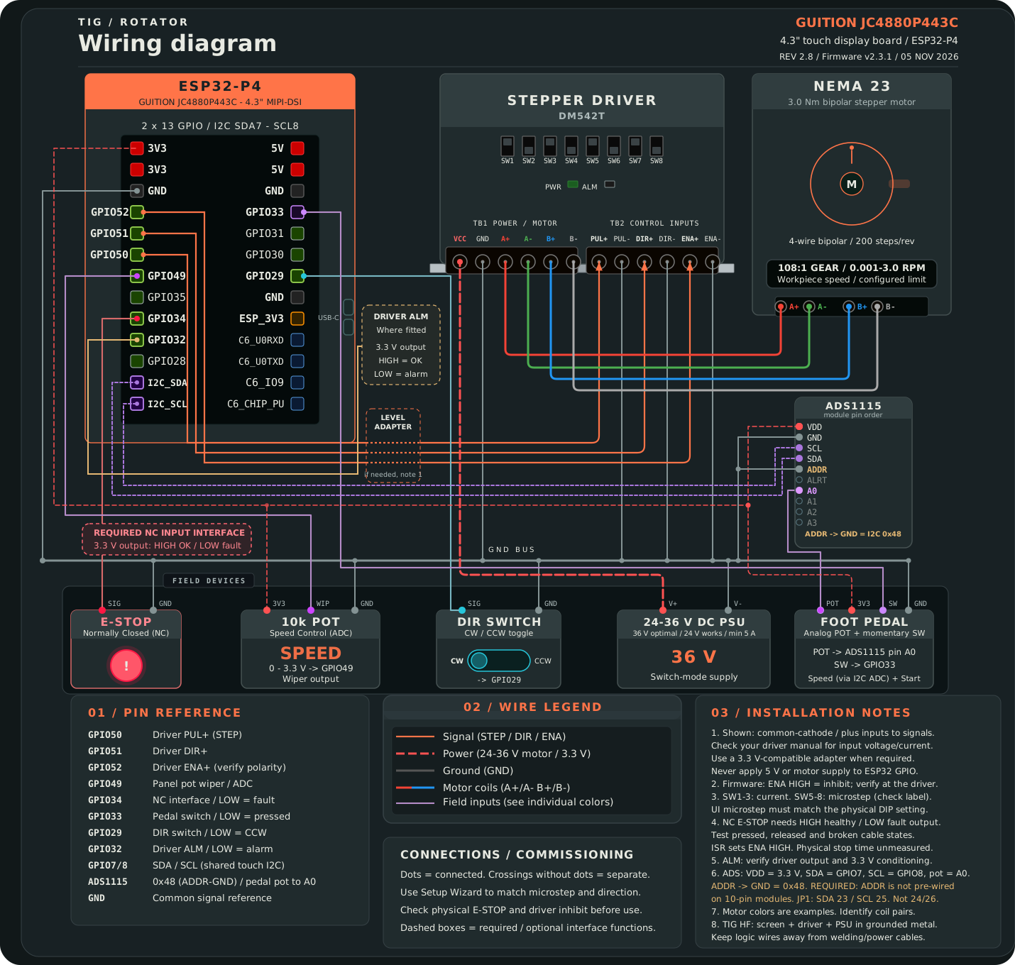
WiringAll wiring goes through the 2 x 13 pin JP1 header. The main pins are STEP GPIO50, DIR GPIO51, ENA GPIO52, pot GPIO49, direction switch GPIO29, E-STOP GPIO34, pedal switch GPIO33, driver alarm GPIO32, and I2C on GPIO7 and GPIO8 for the touch controller and the ADS1115. Grounds for the logic, the driver signal side and the pedal must be common. Do not connect motor VM to the opto inputs.
Full wiring guide: https://github.com/catorendal-a11y/DIY-Welding-Positioner-ESP32-P4/blob/master/docs/HARDWARE_SETUP.md
Wiring diagram (SVG, revision 2.8): https://github.com/catorendal-a11y/DIY-Welding-Positioner-ESP32-P4/blob/master/docs/images/Wiring_diagram.v2.svg
Dashed blocks in the diagram are interface requirements, not verified installed circuitry. The driver routing shown is common-cathode. Confirm the E-STOP interface and ENA polarity on your assembled controller.
Firmware installDownload the release firmware bundle from the v2.4.1 release page and follow the included flashing guide. Check the SHA-256 checksums. Keep motor and driver power off while flashing. The application image goes at 0x10000, never at 0x0.
Update the application only, on a controller that already has this project's partition layout:
python -m esptool --chip esp32p4 --port COM3 write-flash 0x10000 firmware.binReplace COM3 with your port. For a first installation, use the full command in the flashing guide, or build from source with pio run (on Windows, run pio from PowerShell).
Flashing guide: https://github.com/catorendal-a11y/DIY-Welding-Positioner-ESP32-P4/blob/master/docs/releases/FLASHING.md
First runA new installation opens the setup wizard.
- Motor: match driver timing and microsteps, set limits, then Save and apply.
- Direction: hold CW and CCW and watch the workpiece.
- Calibration: move 360 degrees, measure, apply, verify 360 degrees, then save.
- Function check: press and release E-STOP, reset to idle, test Start and Stop.
Setup wizard, step 1. LVGL simulator capture.
The wizard does not measure stop time or certify wiring.
CalibrationCalibration moves the workpiece one full turn, you measure the real result, apply it, then verify and save. The machine has no encoder, so this measurement is the only reference.
Calibration, align step. LVGL simulator capture.
TIG HF enclosure checklist- Controller, driver and motor PSU in one grounded metal enclosure.
- Enclosure bonded to protective earth.
- Motor and power wiring apart from GPIO, ADC, I2C, pedal and E-STOP cables.
- Shielded external cables, ferrites if interference remains.
- Repeat the HF-start checks after changing firmware, wiring or the enclosure.
- I flashed v2.4.1 on my machine on 2026-11-15. Motion, pedal, E-STOP and TIG HF start work.
- Calibration accuracy and stop time are not measured.
- CI runs native tests, simulator self-tests, a layout audit and three firmware builds on every commit.
- The demo video shows real hardware with an earlier UI: https://youtu.be/GygLl6XY-TM
- E-STOP does not cut motor power (see Safety first).
- Pulse programs have no direction control. Direction comes from the Continuous or Step settings.
- A floating pot wiper is not detected, and the analog pedal is not jump-checked.
- Other boards need different drivers and pins.
- No encoder. RPM and progress are calculated.
I want to know if the wiring guide is clear enough to build from. If you build one, or try the Windows simulator, tell me what failed or confused you. Which part of the guide would you rewrite first?
Project website, with the screens, wiring steps and downloads: https://catorendal-a11y.github.io/DIY-Welding-Positioner-ESP32-P4/


Comments