

Hardware components | ||||||
| × | 1 | ||||
| × | 1 | ||||
| × | 1 | ||||
| × | 1 | ||||
| × | 1 | ||||
Software apps and online services | ||||||
 |
| |||||
Or one little step at a time
Introduction
This note illustrates the introductory use of a stepper motor from an Arduino single board microcomputer. It is the third note in a planned series of articles on using motors with micro-computers for electronic projects. Two previous notes illustrated the use of hobby DC motor and servo motor with very simple exercises.
Story
The three basic types of motors used commonly with single board computers are:
- Direct Current (DC)
- Servo
- Stepper
This note is limited to a simple (and single) stepper motor. Future articles will examine operations of these three types of motors in a variety of simple applications.
Stepper Motor
A stepper motor, as the name implies, moves in discrete steps which provide more granular control over the movement than practical in the other two types of motors. There are two key parts in a stepper motor:
- Stator
- Rotor
The stator is the outer pairs of stationary electromagnet coils.
RotorThe rotor is the inner arrangement that rotates along the axis of the shaft. This inner arrangement determines the three types of stepper motors:
- Permanent Magnet
- Variable Reluctance
- Hybrid
As the name implies, a permanent magnet serves as the rotor and the rotation is controlled by stator.
Variable reluctance stepper motorThe rotor in this type of motor uses a ferromagnetic material that induces an electromagnetic field in response to stator’s current flow.
Hybrid stepper motorSince the previous two types of motors have their advantages it is natural to have the combined advantages of both types in the hybrid variation of the motor.
Unipolar or bipolarAnother key characteristic for stepper motors is number of power sources. If there is only one power source then the polarity of the stator is constant and the arrangement is unipolar. If polarity of the stator can be reversed by a secondary power source then the arrangement is bipolar. The model, 28BYJ-48, examined in this note is unipolar.
Test model
The servo motor chosen for the test exercises is 28BYJ-48 (5V DC) which has the following pin connections:
SpecificationsThe key specifications of this stepper motor are tabulated below:
Parameter
Description
Drive mode
Unipolar
Coils
4
Gear ratio
1:64
Step angle, degrees
5.625
Voltage, VDC
5
Current, max, mA
500
The steps required by the motor to complete one full revolution (i.e. 360°) is 360/5.625. The motor requires 64 full revolutions to complete one full revolution of the external shaft (i.e. gear ratio parameter).
Rotation stepsThe key specification for the motor is the gear reduction ratio at 1:64 (In reality, this number could be slightly different depending on the quality of the counterfeit manufacturers but that is a story for another day). Accordingly, for the limited purposes of this starter demonstration exercise, let us assume that there are 64 discrete positions during one full revolution of the internal shaft. The step angle stated on the datasheet is:
α = 5.625°
The steps required by the motor complete one full revolution on the external shaft:
= (360° / 5.625°) * 64 = 4096
Since this particular stepper motor has many counterfeit versions where quality control is non-existent, the gear ratio in the above specifications may not hold true. The number of steps required by the motor to complete one full revolution will not be the same as theoretically estimated above for motors from some suppliers. Please review the reference below on Geared Stepper Motor for the related discussion in the corresponding Arduino forum.
Rotation sequenceThe following table summarizes the sequence to rotate the motor:
Step number
Arduino pin
Output
Wire color
1
2
3
4
5
6
7
8
OUT4
Orange
0
0
1
1
1
1
1
0
OUT3
Yellow
1
0
0
0
1
1
1
1
OUT2
Pink
1
1
1
0
0
0
1
1
OUT1
Blue
1
1
1
1
1
0
0
0
Red
1
1
1
1
1
1
1
1
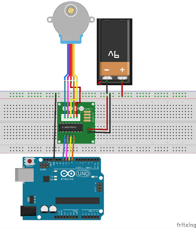
Owing to the power requirements the motor cannot be served directly by the Arduino board. The connection using an interface board and a dedicated power supply for the stepper motor is shown below:
X113647 interface boardThe practical arrangement is to use an interface board as shown below:
The corresponding assembly diagram (within the constraints of the limited purpose of this note) is shown below:
Library
There is a standard library at the Arduino site for use with servo motors – Stepper. The key functions in the library are:
Function
Description
Stepper(steps, pin1, pin2, pin3, pin4)
The constructor method to instantiate an entity object from the class definition for a stepper motor. The parameters are:
steps – number of steps for one revolution of the external shaft of the motor
pin1-pin4 – the reference numbers of the Arduino pins connected to the motor (via the interface board)
setSpeed(speed)
Sets the motor speed in rotations per minute. The method does not rotate the motor. The sole parameter is:
speed - the value of the desired motor speed expressed in rotations per minute
step(value)
Value ranges from 1000 (counter-clockwise) through 1500 (middle) to 2000 (clockwise). Owing to manufacturing challenges some tolerance in these values should be assumed.
Servo
The key functions of this library are:
Part
Description
Quantity
SBC
Arduino UNO R3 single board micro-computer
1
SG90
TowerPro SG90 servo motor, analog
1
Wires
DuPont, male-to-male, 10 cm approx
10
Breadboard
Any standard size
1
Baseplate
Mount computer board and breadboard, optional
1
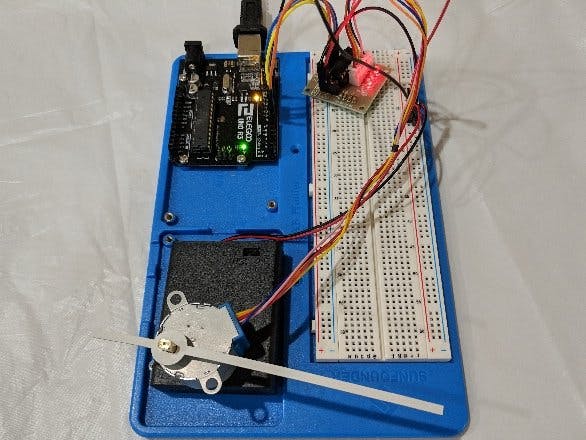
Documenting the Build
All projects in this introductory set of basic and elementary projects, the microcomputer board and the breadboard are mounted on a base-plate. This technique has been illustrated in a previous project and for the sake of brevity will not be repeated here.
The final assembly is shown below:
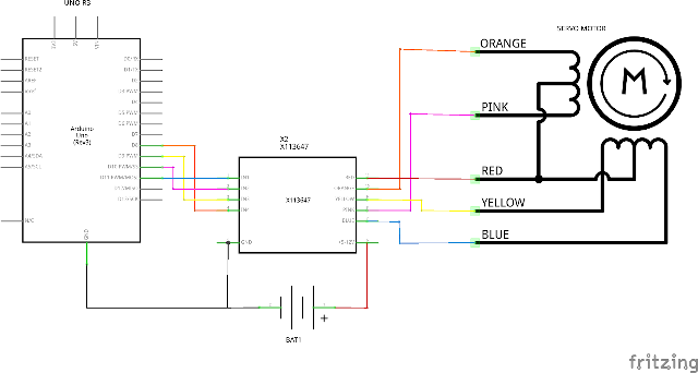
Schematics
The diagram below illustrates a schematic for the elementary exercise to test the servo motor:
An interface board, X11, simplified the test exercises.
Assembly
See above!
Code Name
Stepping Through
Cover image Configurations
There three different arrangements to connect the servo motor to the Arduino board:
- Direct connection to the board for signal, power and ground terminals
- Direct connection as above but using an electrolytic capacitor to minimize current surge when the motor starts
- A separate power supply drives the servo motor
Test Cases
The rotation of the servo motor relying on the standard Arduino Servo library performs the same operations in two ways:
- The application specifies the angular position in degrees
- The application specifies the pulse width that the servo uses to establish the angular positions
Angular position
The following code snippet illustrates the iteration from 0 to 180 degrees for the rotational position:
for (int i=0; i<=180; i+=1)// iterate through all positions from 0 to 180 degrees
  {
    myServo.write(i);      // set the shaft angle to corresponding orientation
    delay(100);            // 100 milliseconds hold for test use only
  }
The following code snippet illustrates the iteration from minimum to maximum pulse width (which in turn represents the available angle of rotation for the servo motor):
 for (int i=pwMin; i<=pwMax; i+=1) // iterate through all pulse width values from pwMin to pwMax
  {
    myServo.writeMicroseconds(i);   // set pulse width for desired angle and rotate shaft to corresponding position
    delay(5);                       // 100 milliseconds hold for test use only
  }
References
Operation principle of stepper motor
https://42bots.com/tutorials/28byj-48-stepper-motor-with-uln2003-driver-and-arduino-uno/
https://www.elecrow.com/wiki/index.php?title=ULN2003_Stepper_Motor_Driver
X113647 stepper motor interface board
Toshiba ULN2003APG datasheet (end-of-life)
TBD62003APG datasheet (successor to ULN2003APG)


Comments