


Hardware components | ||||||
| × | 2 | ||||
 |
| × | 1 | |||
 |
| × | 1 | |||
 |
| × | 2 | |||
| × | 1 | ||||
Software apps and online services | ||||||
 |
| |||||
I built a new home where water is a persistent problem. To mitigate the chances of a flooded basement, I needed a system to notify me in case of a sump pump failure or a power outage so I can react in time.
Because of the rural location of my home and spotty cell phone service, I could not rely on the push notifications from a home automation hub (because push notifications are not queued and are lost if your mobile data service is spotty).
So I built my own solution.
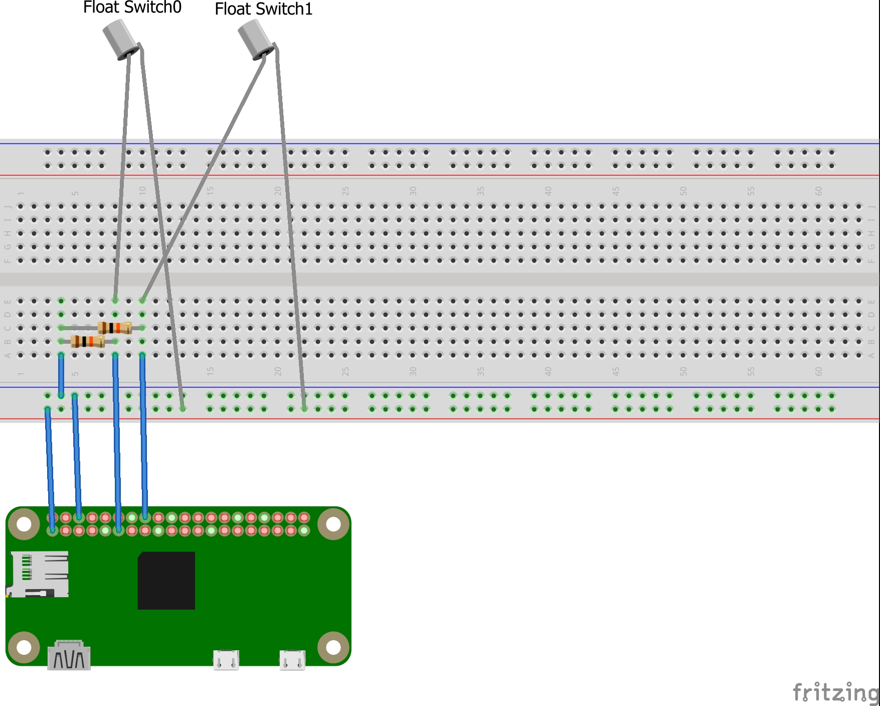
This solution uses a Raspberry Pi GPIO to monitor a pair of float switches. One switch is placed between the high and low water mark in your sump so that it toggles every time the sump fills and drains as the pump does it's thing. The second switch is placed above the high water mark so that there's an alarm if the water reaches a level where it is certain that power or pump has failed.
A very flexible daemon was written in C to manage the system. It allows you to configure any number of float switches and perform any action when a switch is toggled, or if there's a change in the amount of water entering the sump, or if the sump pump is overdue to evacuate the sump. It could even be used to switch a relay to engage an emergency backup pump.
AssumptionsThese instructions assume that you're able to power up your Raspberry Pi, install Raspbian, connect to your network, and have a basic understanding of Linux (can sudo, navigate the filesystem, use apt-get).
1. Measure your sump pitThis solution works best when you're able to provide it with all the dimensions of your sump, and when you know the high (water level where your sump pump activates) and low (water level where your sump pump stops pumping) water marks. This information is used by the application to calculate how fast water is entering your sump, how much water is in your sump, and what the capacity of your sump is so that it can estimate how much time you have to react to a failure.
The application uses millimeters.
My sump dimensions are:
- Diameter=510mm
- Depth=760mm
- Low water mark from bottom of sump pit=114mm
- High water mark from bottom of sump pit=222mm
For my prototype, I used a plastic rod. You can use anything you like. A fibreglass driveway marker, a small piece of water pipe, etc would work also. The best, but most difficult, option is to use a piece of pipe 2 inches in diameter or larger and assemble the switches inside the pipe. This ensures that wires and debris in the sump pit do not encumber the float switches and interfere with the proper function of the switches any way.
Attach the float switches. Switch0 needs to be somewhere between the low and high water levels so that it toggles on as the water level rises, and off again when the sump pump evacuates the water. Switch1 needs to be above the high water mark. Switch1 is used to detect when something has gone wrong.
Make sure the float switches are installed correctly. Some float switches are open (off) when submerged and some are closed (on) when submerged. If the switch is open when submerged, install it upside down so that it is open when not submerged. Sometimes this can be accomplished by removing and flipping the float only. Also test the switches before you install them so you don't have to disassemble things later. If you find after the fact that the switches are upside down, you can flip them logically in the configuration file with "Switch0Invert=true".
Splice and run the wires to the top of the measuring stick. I removed the insulation from an old Cat5 Ethernet cable and used the small wires within to extend the short wires on the float switches, making sure to use something like heat-shrink to seal the joints. Wrap the wires up neatly so that they cannot tangle or encumber the smooth operation of the float switches.
Using the wiring schematic, connect the switches to the Raspberry Pi GPIO.
If you haven't already done so, install Raspbian or any other Linux flavor on your Pi and configure it to connect to your network.
Mount the Pi to the top of your dip stick.
On the Raspberry Pi, create a configuration file at /etc/sumpalarm.conf, or modify the sample config file provided.
Make sure the configured sump geometry matches your measurements from step 1.
Configure the behaviour you would like when the switches toggle, when the rate changes, or the pump is overdue to evacuate. Use the example config file as guidance. There are a number of parameters and features documented in the sample config.
If you want to use e-mail like the example config, you must make sure that a mail client is installed and set up. In my example I use GNU Mail and ssmtp (apt-get install mailutils ssmtp). Test it before you rely on it.
5. CompileCompile the application with:
gcc SumpAlarm.cpp bcm2835.c bcm2835.h -o sumpalarm
You can also use g++ with -fpermissive but a few warnings will be produced.
6. Install the system into the sump and executeFor testing, you can run the application with a -v switch (./sumpalarm -v) so that it runs in the console and outputs information to the screen. Under normal circumstances however, the application will run as a daemon in the background and log to /var/log/sumpalarm.log. If you run without the -v switch, it will appear to immediately terminate. This is not the case, you can use "ps -A | grep sumpalarm" to verify that the application is running, or view the log file to see that startup was successful.
I placed the system on a UPS, along with my wireless router and modem to make sure that a power failure will not prevent alerts from being sent to my phone from the Pi.
There's not really any limit to what you can do to customise this system.
You may also want to use the system to activate a backup pump in case of emergency. You can accomplish this by connecting a relay to another GPIO pin and turn it on or off using a Python script, executed by the Switch1On action script and off again with the Switch0Off action script, as an example.
Despite the simplistic nature of float switches in this sort of arrangement, it is trivial to gather some interesting data. It is possible to observe how ground tides, precipitation events, and human activity, affects groundwater.
This graph, showing that there is a daily rise and fall in groundwater that could possibly be daily activity around the home putting pressure on the ground, increased movement of groundwater with daily temperature changes, or even Earth tides.
The sample config includes a Switch0On action script that logs the date and time and rate of inflow into the sump each time Switch0 is toggled on. This can be retrieved from the Pi with scp (Linux) or pscp (Windows) and opened using Excel, LibreOffice, Google Sheets, etc. and charted just as shown (Excel was used in this case).
You can also gather weather data and see how it correlates to these data points. For example, Environment Canada has a weather station at a nearby airport and with a little bit of ingenuity you can use wget to capture the current conditions directly from the weather station and include it in your CSV.
/* SumpAlarm.cpp - Service that monitors simple float switches and alarms if
a sump pump appears to have failed.
No guarantees are given or implied. Damages resulting from bugs, faults, or
malfunctions of this application are not the responsibility of the author.
Use at your own risk.
Usage:
sumpalarm [-v]
If used without the -v option, the application is run as a daemon and
will produce no output.
Using -v will execute the application in the console and write to stdout
as opposed to a log file.
The expected configuration includes two float switches.
Switch0 to be placed between the low and high water mark in the sump pit
so that it is tripped with the same frequency as the pump engages.
Switch1 to be placed slightly above the high water mark so that it is
activated reasonably quickly after a pump or power failure.
Action scripts to be executed as follows:
Switch0On The lower switch is activated. This will happen frequently and
is not intended to generate an alarm. It is intended to be used
for an informational push such as output to file or syslog or
record a database entry for gathering statistics.
Switch0Off The lower switch has switched off
Switch1On In the intended configuration, this switch will only be activated
in the event of a power or pump failure. This is a critical alarm
Switch1Off Power or pump function restored, crisis averted.
Switch2On Made available for additional redundant switches or additional
sump pits up to Switch99
Switch2Off ...
RateChange There's a sudden change in flow rate as per Switch0 toggle
frequency. Could be a rain storm, overland flooding instead of
ground water, or an exterior sump has failed and this one is
running more frequently to catch up.
Overdue If Switch0 is active and has remained active for longer than
expected, according to the running average frequency + the
OverdueThreshold parameter, this script executes as a means of
providing early warning that there may be a problem with power or
pump.
Environment variables to be set for use in action scripts:
SAVOLUME An integer representing the current estimated volume of water in
the sump pit at a given time. Calculated using SwitchXLevel and
SumpDiameter
SARATE An integer representing the number of Litres of water per hour
currently flowing into the sump pit. Calculated using the time
between Switch0 off (low water) mark and Switch0 on (Switch0Level)
mark, and the diameter of the sump pit (SumpDiameter).
0 does not necessarily mean that there is no water entering the
sump pit. It may also mean that the necessary parameters are not
provided.
SAFREQ An integer representing the number of seconds between Switch0 ON
events, on a running average of FREQ_HISTORY instances.
SAFREQM An integer representing the number of minutes between Switch0 ON
events, on a running average of FREQ_HISTORY instances
SATIMELEFT An integer representing the estimated number of minutes before the
available capacity of the sump pit is filled. This is a VERY rough
estimate as weeping tile will add additional capacity and
groundwater in-flow will slow as it gets nearer to the groundwater
level surrounding the building
SATIMELEFTM Same as above but in minutes
Relies on a config file being present at /etc/sumpalarm.conf
Configuration file example:
# SumpAlarm Sample Config File. Parameters here are case sensitive and will
# not be parsed correctly if the case is incorrect.
# LogFile should be the first entry. Otherwise a default log file will
# be created before the LogFile line is reached.
# Logging Levels:
# 0=Log nothing
# 1=Log errors
# 2=Log errors, switch toggles, and config changes
# 3=Log Everything
LogFile=/var/log/sumpalarm.log
LogLevel=3
# This section is used when an alarm is produced, to estimate the volume
# of water that the sump is taking on at the time and how much time is
# available before water will breach the sump measurements in cm, volume in L
SumpDepth=760
SumpDiameter=510
LowWater=114
HighWater=222
# This section defines the activation depth of the float switches, in cm from
# the bottom of the sump, the GPIO Pin that is used as input, and
# followed by the action scripts. Up to Switch99 is permitted so long as GPIO
# supports it.
Switch0Level=200
Switch0Pin=14
Switch0Bounce=5
Switch0On=echo $(date) Switch0On Flow Rate $SARATE L/H Frequency $SAFREQ >> SumpAlarm.log
Switch0Off=echo $(date) Switch0Off Flow Rate $SARATE L/H Frequency $SAFREQ >> SumpAlarm.log
Switch1Level=300
Switch1Pin=15
Switch1Bounce=5
Switch1On=echo SUMP FAILURE! $SATIMELEFTM Minutes before flooding! | mail omgomgomg@sumpalarm.com -s "Sump Failure"
Switch1Off=echo SUMP Restored. Water level receding | mail omgomgomg@sumpalarm.com -s "Sump Restored"
# This action script executes when the frequency of pump activations changes
# by more than a configured percentage
RateChangeAmt=20
RateChange=echo The rate of flow has changed by 20 percent since last notice. New rate $SARATE Litres per hour | mail info@sumpalarm.com -s "Sump Rate Changed"
# This script executes if Switch0On is overdue by the 'OverdueThreshold' number of seconds beyond the running average
OverdueThreshold=120
Overdue=echo Warning: Sump evacuation is overdue. Possible power or pump failure | mail info@sumpalarm.com -s "Pump activation overdue"
*******************************************************************************
Compile: gcc SumpAlarm.cpp bcm2835.c bcm2835.h -o sumpalarm
Revision History
Date Author Notes
May 11-15, 2017 Cory Whitesell Original application development and testing
May 18, 2017 Cory Whitesell Updated to reload action scripts following config changes
May 24, 2017 Cory Whitesell Bug fixes, better control of logging, converted to millimeters as opposed to centimeters for dimensions, for greater accuracy
June 20, 2017 Cory Whitesell Added Overdue action script and OverdueThreshold parameter. Previous build has run stable for 26 days when stopped for the update
*/
#include <stdio.h>
#include <string.h>
#include <stdlib.h>
#include <dirent.h>
#include <fcntl.h>
#include <assert.h>
#include <time.h>
#include <unistd.h>
#include <signal.h>
#include "bcm2835.h"
#include <sys/types.h>
#include <sys/stat.h>
// Defaults
#define CONFIGFILE "/etc/sumpalarm.conf"
#define LOGFILE "/var/log/sumpalarm.log"
#define FREQ_HISTORY 4
#define BOUNCEDELAY 5
#define BCM2708_PERI_BASE 0x20000000
#define GPIO_BASE BCM2708_PERI_BASE + 0x200000) /* GPIO controller */
void trim(char *s);
int sa_strcmp(char *s1, const char *s2); // compare two strings. If the first non-matching character is a null terminator, strings are considered equal (return 0)
void SetEnvironment(struct FloatSwitch s,struct ConfigData cd);
int GetFrequency(struct FloatSwitch s); // get an average frequency at which the sump is running, in seconds
void Action(char *action);
void RefreshConfig(struct ConfigData &cd, bool initial);
void WriteLog(const char *entry,int level);
struct FloatSwitch
{
int initialized; // 1=true
int level;
int pin; // GPIO PIN associated with this switch
char *OnAction; // Action string to execute when turned on
char *OffAction; // Action string to execute when turned off
int freq[FREQ_HISTORY]; // history of seconds between activations
int lastfreq; // the last frequency that was reported
int state; // 1 on, 0 off
time_t LastOn; // the last time the pump switch activated
time_t LastOff;
int bouncedelay; // time to wait before recognizing a switch toggle
};
struct ConfigData {
int sumpdepth;
int sumpdiameter;
int lowwater;
int highwater;
int capacity;
int vol;
int rate;
int freq;
int ratechangeamt;
char *ratechange;
struct FloatSwitch switchlist[100];
int overduethreshold;
char *overdue;
};
bool Terminated=false;
bool verbose=false;
int LogLevel=3; // default to log everything
char LogFileName[1000]=LOGFILE;
char logme[960];
// Handler for signals from OS so that the application can exit gracefully if terminated
void INTHandler(int sig)
{
char c;
signal(sig, SIG_IGN);
// ctrl-c
if (sig==SIGINT)
{
WriteLog("Process terminated by user.",1);
Terminated=true;
return;
}
// system shutdown or session terminated
if (sig==SIGTERM)
{
WriteLog("Process terminated by system.",1);
Terminated=true;
return;
}
// process killed with pskill
if (sig==SIGKILL||sig==SIGHUP)
{
WriteLog("Process killed by system.",1);
Terminated=true;
return;
}
// Program caused a segmentation fault. Best to catch it than to inexplicably terminate
if (sig==SIGSEGV)
{
WriteLog("Segmentation fault.",1);
Terminated=true;
return;
}
}
int main(int argc, char **argv)
{
// check for a -v switch. By default this will run as a daemon and does not
// produce output to stdout or stderr. But if -v is specified it will run
// in the terminal
if (argc>=2)
{
if (strcmp(argv[1],"-v")==0)
verbose=true;
}
else
{
// fork the process to spawn a daemon (service)
pid_t dpid=fork();
pid_t session_id;
// if the daemon fails to fork
if (dpid < 0)
{
printf("Unable to initialize Daemon\n");
exit(1);
}
if (dpid > 0) exit(0); // terminate original process indicating the daemon is started
umask(0);
session_id=setsid(); // give the daemon a session ID
if (session_id <0) exit(1);
// this service will not have any interaction with a terminal, so close the streams
close(STDIN_FILENO);
close(STDOUT_FILENO);
close(STDERR_FILENO);
}
// since we will be in an infinite loop, monitor signals to detect interruptions such as ctrl-c
signal(SIGINT,INTHandler);
signal(SIGTERM,INTHandler);
signal(SIGKILL,INTHandler);
signal(SIGSEGV,INTHandler);
// Since we will be forking system calls, we will tell the OS that we're a terrible parent
// and don't care about the welfare of our children. This prevents <defunct>
// processes resulting from forks
signal(SIGCHLD, SIG_IGN);
// initialize the GPIO
if (!bcm2835_init())
{
WriteLog("Unable to initialize GPIO. Use sudo.",1);
return 2;
}
// Declare and initialize non-switch related variables
int ID, i;
char cline[65536];
// temp variables
int state=0;
int freqtemp=0;
bool overduenotice=false;
struct ConfigData cd;
// sump dimensions
cd.sumpdepth=0;
cd.sumpdiameter=0;
cd.lowwater=0;
cd.highwater=0;
cd.ratechange=NULL;
cd.ratechangeamt=0;
cd.overduethreshold=0;
cd.overdue=NULL;
time_t t;
time_t LastConfigCheck;
time(&LastConfigCheck);
// set all switches to uninitialized and initialize other variables to zero/NULL
for (ID=0;ID<100;ID++)
{
cd.switchlist[ID].initialized=0;
cd.switchlist[ID].OnAction=NULL;
cd.switchlist[ID].OffAction=NULL;
cd.switchlist[ID].level=0;
cd.switchlist[ID].pin=0;
for (i=0;i<FREQ_HISTORY;i++)
cd.switchlist[ID].freq[i]=0;
cd.switchlist[ID].lastfreq=0;
cd.switchlist[ID].state=0;
cd.switchlist[ID].LastOn=(time_t)0;
cd.switchlist[ID].LastOff=(time_t)0;
cd.switchlist[ID].bouncedelay=BOUNCEDELAY;
}
RefreshConfig(cd,true);
if (cd.switchlist[0].initialized==0)
{
WriteLog("Error: Switch0 is not configured. Terminating.",1);
return 1;
}
// configure input pins and read initial state
for (ID=0;ID<100;ID++)
{
if (cd.switchlist[ID].initialized)
{
bcm2835_gpio_fsel(cd.switchlist[ID].pin, BCM2835_GPIO_FSEL_INPT);
cd.switchlist[ID].state=bcm2835_gpio_lev(cd.switchlist[ID].pin);
snprintf(logme,939,"Switch%d Initial state: ",ID);
if (cd.switchlist[ID].state==HIGH) strcat(logme,"On");
else strcat(logme,"Off");
WriteLog(logme,3);
}
}
char envstr[1000];
if (verbose) WriteLog("Application started",3);
else WriteLog("Daemon started",3);
while (!Terminated)
{
time(&t);
// Run the "Overdue" script is the conditions are met. Should Only run once until the situation is resolved rather than every few seconds
if (cd.switchlist[0].state==HIGH&&overduenotice==false) // improve the performance by splitting conditionals so that the difficult ones aren't evaluated unless necessary
{
freqtemp=GetFrequency(cd.switchlist[0]);
if (t-cd.switchlist[0].LastOff>=freqtemp+cd.overduethreshold&&freqtemp!=0)
{
overduenotice=true;
Action(cd.overdue);
}
}
// check to see if the configuration file has been changed and needs to be reloaded
if (t-LastConfigCheck>180) // 3 minutes
{
LastConfigCheck=t;
RefreshConfig(cd,false);
}
// loop through the initialized switches to see if the state has changed on any of them
for (ID=0;ID<100;ID++)
{
if (cd.switchlist[ID].initialized)
{
state=bcm2835_gpio_lev(cd.switchlist[ID].pin);
if (state!=cd.switchlist[ID].state)
{
// switch has changed to 'On'
if (state==HIGH)
{
// don't react if the bounce delay hasn't expired
if (t-cd.switchlist[ID].LastOff<cd.switchlist[ID].bouncedelay) continue;
cd.switchlist[ID].state=HIGH;
snprintf(logme,939,"Switch%d On",ID);
WriteLog(logme,2);
for (i=0;i<FREQ_HISTORY-1;i++)
cd.switchlist[ID].freq[i]=cd.switchlist[ID].freq[i+1];
if (cd.switchlist[ID].LastOn!=0) // prevent logging if this is the first entry since startup
cd.switchlist[ID].freq[FREQ_HISTORY-1]=t-cd.switchlist[ID].LastOn;
cd.switchlist[ID].LastOn=t;
cd.freq=GetFrequency(cd.switchlist[0]);
SetEnvironment(cd.switchlist[0],cd);
Action(cd.switchlist[ID].OnAction);
if (ID==0&&cd.freq!=0&&cd.ratechange!=NULL)
{
if (cd.switchlist[0].lastfreq==0)
{
int z=0;
// only send rate if we've seen FREQ_HISTORY cycles so far
for (i=0;i<FREQ_HISTORY;i++)
if (cd.switchlist[0].freq[i]==0) z++;
if (z==0)
{
Action(cd.ratechange);
cd.switchlist[0].lastfreq=cd.freq;
}
}
else
{
double rat=(double)cd.switchlist[0].lastfreq/(double)cd.freq;
if (rat>(1.0+(double)cd.ratechangeamt/100)||rat<(1.0-(double)cd.ratechangeamt/100))
{
Action(cd.ratechange);
cd.switchlist[ID].lastfreq=cd.freq;
}
}
}
}
else // switch has changed to 'Off'
{
// don't react if the bounce delay hasn't expired
if (t-cd.switchlist[ID].LastOff<cd.switchlist[ID].bouncedelay) continue;
if (ID==0) overduenotice=false;
snprintf(logme,939,"Switch%d Off",ID);
WriteLog(logme,2);
cd.switchlist[ID].state=state;
cd.switchlist[ID].LastOff=t;
SetEnvironment(cd.switchlist[0],cd);
Action(cd.switchlist[ID].OffAction);
}
}
}
}
// release the processor for a second before scanning again
sleep(1);
}
// free allocated space
for (ID=0;ID<100;ID++)
{
if (cd.switchlist[ID].OnAction!=NULL) free(cd.switchlist[ID].OnAction);
if (cd.switchlist[ID].OffAction!=NULL) free(cd.switchlist[ID].OffAction);
}
if (cd.ratechange!=NULL) free(cd.ratechange);
if (cd.overdue!=NULL) free(cd.overdue);
return 0;
}
void trim(char *s)
{
// trim leading and trailing white space from a string
int textstart=-1;
int i,len;
len=strlen(s);
// find where the printable text starts
for (i=0;i<len;i++)
{
if (s[i]=='\t'||s[i]=='\n'||s[i]=='\r'||s[i]==' '||s[i]=='\t')
continue;
else
{
textstart=i;
break;
}
}
// no printable text
if (textstart==-1)
{
s[0]=0;
return;
}
// leading whitespace present
if (textstart>0)
{
for (i=0;i<len-textstart;i++)
s[i]=s[i+textstart];
s[len-textstart]=0;
}
// work back from end to find last printable character
for (i=len-1;i>0;i--)
{
if (s[i]=='\t'||s[i]=='\n'||s[i]=='\r'||s[i]==' '||s[i]=='\t')
continue;
else
{
s[i+1]=0;
break;
}
}
}
// Custom string comparison function.
// Compares only to the end of the shortest string ("Hello" == "Hello World!")
// Case insensitive
int sa_strcmp(char *s1, const char *s2)
{
unsigned int i;
int diff;
unsigned int len=strlen(s1);
if (len>strlen(s2)) len=strlen(s2);
for (i=0;i<len;i++)
{
diff=s1[i]-s2[i];
diff=s1[i]-s2[i];
if (diff==0||(diff==32&&s1[i]>='a'&&s1[i]<='z')||(diff==-32&&s1[i]>='A'&&s1[i]<='Z'))
continue;
return s1[i]-s2[i];
}
return 0;
}
// Set environment variables in advance of running an action script
void SetEnvironment(struct FloatSwitch s,struct ConfigData cd)
{
char envstr[1000];
int timeleft;
snprintf(envstr,999,"%d",cd.freq);
setenv("SAFREQ",envstr,1);
snprintf(envstr,999,"%dm %ds",cd.freq/60,cd.freq%60);
setenv("SAFREQF",envstr,1);
cd.vol=((s.level/10.0)*(3.14159265*(cd.sumpdiameter/20.0)*(cd.sumpdiameter/20.0)))/1000.0;
snprintf(envstr,999,"%d",cd.vol);
setenv("SAVOLUME", envstr,1);
if (cd.freq!=0)
cd.rate=(((cd.highwater-cd.lowwater)/10.0*(3.14159265*(cd.sumpdiameter/20.0)*(cd.sumpdiameter/20.0)))/1000.0)*3600/cd.freq;
else cd.rate=0;
snprintf(envstr,999,"%d",cd.rate);
setenv("SARATE",envstr,1);
if (cd.rate==0) timeleft=0;
else timeleft=(cd.capacity-cd.vol)*3600/cd.rate;
snprintf(envstr,999,"%d",timeleft);
setenv("SATIMELEFT",envstr,1);
snprintf(envstr,999,"%d",timeleft/60);
setenv("SATIMELEFTM",envstr,1);
}
// determine the frequency of activations for the selected switch
int GetFrequency(struct FloatSwitch s)
{
int f=0;
int z=0;
for (int i=0;i<FREQ_HISTORY;i++)
{
f+=s.freq[i];
if (s.freq[i]==0) z++;
}
if (z!=FREQ_HISTORY) f=f/(FREQ_HISTORY-z);
return f;
}
// Execute an action script in a forked process to avoid slow scripts interfering with intended application behavior
void Action(char *action)
{
if (action==NULL) return;
#ifdef DEBUG
snprintf(logme,939,"Executing Action \"%s\"",action);
WriteLog(logme,3);
#endif
// fork and forget
pid_t pid=fork();
if (pid==0)
{
system(action);
exit(0);
}
}
void RefreshConfig(struct ConfigData &cd, bool initial)
{
static char hash[65]="";
int ID;
char cline[65535];
if (!initial)
{
// decide whether the config has changed
system("sha256sum /etc/sumpalarm.conf > ./configsum");
FILE *check=fopen("./configsum","r");
if (check==NULL) return;
fgets(cline,64,check);
cline[64]=0;
fclose(check);
if (strcmp(hash,cline)==0) return; // no change to config
WriteLog("Config changed",2);
snprintf(logme,939,"Old: %s",hash);
WriteLog(logme,2);
snprintf(logme,939,"New: %s",hash,cline);
WriteLog(logme,2);
memcpy((void *)hash,(void *)cline,64);
hash[64]=0;
}
else
{
// remember the checksum of the config file upon first load
system("sha256sum /etc/sumpalarm.conf > ./configsum");
FILE *check=fopen("./configsum","r");
if (check==NULL) return;
fgets(cline,64,check);
cline[64]=0;
fclose(check);
memcpy((void *)hash,(void *)cline,64);
hash[64]=0;
WriteLog("Reading Config...",3);
}
FILE *conf=fopen(CONFIGFILE,"r");
if (conf==NULL)
{
// if the file is locked or missing, it is a problem on startup but not during execution
if (initial)
{
WriteLog("Unable to open config file /etc/sumpalarm.conf",1);
exit(1);
}
else return;
}
// read each line of configuration
while (fgets(cline,65534,conf)!=NULL)
{
trim(cline); // remove leading or trailing whitespace from config line
// if the line is blank or if the line is a comment, move to the next line
if (strlen(cline)<1) continue;
if (cline[0]=='#') continue;
if (sa_strcmp(cline,"LogLevel")==0)
{
// remove whitespace around '=' (SumpDepth = x --> SumpDepth=x)
trim(cline+8);
trim(cline+9);
LogLevel=atoi(cline+9);
if (LogLevel>3||LogLevel<0) LogLevel=3;
snprintf(logme,939,"Logging level %d set",LogLevel);
WriteLog(logme,3);
continue;
}
if (sa_strcmp(cline,"LogFile")==0)
{
// remove whitespace around '=' (SumpDepth = x --> SumpDepth=x)
trim(cline+7);
trim(cline+8);
strncpy(LogFileName,cline+8,999);
snprintf(logme,939,"LogFile set: %s",LogFileName);
WriteLog(logme,3);
continue;
}
// Sump pit sizing parameters
if (sa_strcmp(cline,"SumpDepth")==0)
{
if (!initial) continue; // only load action scripts if not initial load
// remove whitespace around '=' (SumpDepth = x --> SumpDepth=x)
trim(cline+9);
trim(cline+10);
cd.sumpdepth=atoi(cline+10);
snprintf(logme,939,"SumpDepth set to %d",cd.sumpdepth);
WriteLog(logme,3);
continue;
}
if (sa_strcmp(cline,"SumpDiameter")==0)
{
if (!initial) continue; // only load action scripts if not initial load
// remove whitespace around '='
trim(cline+12);
trim(cline+13);
cd.sumpdiameter=atoi(cline+13);
snprintf(logme,939,"SumpDiameter set to %d",cd.sumpdiameter);
WriteLog(logme,3);
continue;
}
if (sa_strcmp(cline,"LowWater")==0)
{
if (!initial) continue; // only load action scripts if not initial load
// remove whitespace around '='
trim(cline+8);
trim(cline+9);
cd.lowwater=atoi(cline+9);
snprintf(logme,939,"LowWater set to %d",cd.lowwater);
WriteLog(logme,3);
continue;
}
if (sa_strcmp(cline,"HighWater")==0)
{
if (!initial) continue; // only load action scripts if not initial load
// remove whitespace around '='
trim(cline+9);
trim(cline+10);
cd.highwater=atoi(cline+10);
snprintf(logme,939,"HighWater set to %d",cd.lowwater);
WriteLog(logme,3);
continue;
}
if (sa_strcmp(cline,"RateChangeAmt")==0)
{
// remove whitespace around '='
trim(cline+13);
trim(cline+14);
cd.ratechangeamt=atoi(cline+14);
snprintf(logme,939,"Rate Change percentage set to %d",cd.ratechangeamt);
WriteLog(logme,3);
continue;
}
if (sa_strcmp(cline,"OverdueThreshold")==0)
{
// remove whitespace around '='
trim(cline+16);
trim(cline+17);
cd.overduethreshold=atoi(cline+17);
snprintf(logme,939,"Rate Change percentage set to %d",cd.overduethreshold);
WriteLog(logme,3);
continue;
}
if (sa_strcmp(cline,"RateChange")==0)
{
// remove whitespace around '='
trim(cline+10);
trim(cline+11);
if (strlen(cline+11)<=0) continue;
if (cd.ratechange!=NULL)
{
if (strcmp(cd.ratechange,cline+11)==0) continue;
else
{
free(cd.ratechange);
cd.ratechange=(char *)malloc(strlen(cline+11)+1);
strcpy(cd.ratechange,cline+11);
}
}
else
{
cd.ratechange=(char *)malloc(strlen(cline+11)+1);
strcpy(cd.ratechange,cline+11);
}
snprintf(logme,939,"Rate Change command string set: %s",cd.ratechange);
WriteLog(logme,3);
continue;
}
if (sa_strcmp(cline,"Overdue")==0&&sa_strcmp(cline,"OverdueT")!=0)
{
// remove whitespace around '='
trim(cline+7);
trim(cline+8);
if (strlen(cline+8)<=0) continue;
if (cd.overdue!=NULL)
{
if (strcmp(cd.overdue,cline+8)==0) continue;
else
{
free(cd.overdue);
cd.overdue=(char *)malloc(strlen(cline+8)+1);
strcpy(cd.overdue,cline+8);
}
}
else
{
cd.overdue=(char *)malloc(strlen(cline+8)+1);
strcpy(cd.overdue,cline+8);
}
snprintf(logme,939,"Overdue command string set: %s",cd.overdue);
WriteLog(logme,3);
continue;
}
if (sa_strcmp(cline,"Switch")==0)
{
// Determine ID of switch
if (cline[6]<'0'||cline[6]>'9')
continue; // Invalid (non numeric) switch ID
ID=cline[6]-'0';
if (cline[7]>='0'&&cline[7]<='9')
ID=ID*10+(cline[7]-'0'); // 2-digit switch ID
int digits=1; // note the number of digits in the Switch ID for parsing
if (ID>9)digits=2;
// determine which parameter of the switch is being set
if (sa_strcmp(cline+6+digits,"Level")==0)
{
trim(cline+11+digits);
trim(cline+12+digits);
cd.switchlist[ID].level=atoi(cline+12+digits);
snprintf(logme,939,"Switch %d Level set: %d",ID,cd.switchlist[ID].level);
WriteLog(logme,3);
continue;
}
if (sa_strcmp(cline+6+digits,"Pin")==0)
{
if (!initial) continue;
trim(cline+9+digits);
trim(cline+10+digits);
cd.switchlist[ID].pin=atoi(cline+10+digits);
// validate value
if (cd.switchlist[ID].pin!=0)
{
// a switch is only considered initialized when a Pin number has been set
cd.switchlist[ID].initialized=1;
snprintf(logme,939,"Switch %d Pin set: %d",ID,cd.switchlist[ID].pin);
WriteLog(logme,3);
continue;
}
else
{
snprintf(logme,939,"Switch%d GPIO PIN invalid");
WriteLog(logme,1);
exit(1);
}
}
if (sa_strcmp(cline+6+digits,"Bounce")==0)
{
trim(cline+12+digits);
trim(cline+13+digits);
cd.switchlist[ID].bouncedelay=atoi(cline+13+digits);
snprintf(logme,939,"Switch %d Bounce Delay set: %d",ID,cd.switchlist[ID].bouncedelay);
continue;
}
if (sa_strcmp(cline+6+digits,"On")==0)
{
trim(cline+8+digits);
trim(cline+9+digits);
if (strlen(cline+9)<=0) continue;
if (cd.switchlist[ID].OnAction!=NULL)
{
if (strcmp(cd.switchlist[ID].OnAction,cline+9)==0) continue;
else
{
free(cd.switchlist[ID].OnAction);
cd.switchlist[ID].OnAction=(char *)malloc(strlen(cline+9+digits)+1);
strcpy(cd.switchlist[ID].OnAction,cline+9+digits);
}
}
else
{
cd.switchlist[ID].OnAction=(char *)malloc(strlen(cline+9+digits)+1);
strcpy(cd.switchlist[ID].OnAction,cline+9+digits);
}
snprintf(logme,939,"Switch %d On Action set: %s",ID,cd.switchlist[ID].OnAction);
WriteLog(logme,3);
continue;
}
if (sa_strcmp(cline+6+digits,"Off")==0)
{
trim(cline+9+digits);
trim(cline+10+digits);
if (strlen(cline+10)<=0) continue;
if (cd.switchlist[ID].OffAction!=NULL)
{
if (strcmp(cd.switchlist[ID].OffAction,cline+10)==0) continue;
else
{
free(cd.switchlist[ID].OffAction);
cd.switchlist[ID].OffAction=(char *)malloc(strlen(cline+10+digits)+1);
strcpy(cd.switchlist[ID].OffAction,cline+10+digits);
}
}
else
{
cd.switchlist[ID].OffAction=(char *)malloc(strlen(cline+10+digits)+1);
strcpy(cd.switchlist[ID].OffAction,cline+10+digits);
}
snprintf(logme,939,"Switch %d Off Action set: %s",ID,cd.switchlist[ID].OffAction);
WriteLog(logme,3);
continue;
}
}
}
fclose(conf);
cd.capacity=(3.14159265*(cd.sumpdiameter/20.0)*(cd.sumpdiameter/20.0)*(cd.sumpdepth/10.0))/1000.0;
snprintf(logme,939,"Capacity set to %d Litres",cd.capacity);
WriteLog(logme,3);
}
// Write a log entry to file or to the console if running verbose
void WriteLog(const char *entry,int level)
{
time_t lt;
time(<);
char logtime[40],logentry[1000];
strftime(logtime, 39, "%Y-%m-%d %T", localtime(<));
snprintf(logentry,999,"%s,\"%s\"\n",logtime,entry);
if (!verbose&&level<=LogLevel)
{
FILE *logfile=fopen(LogFileName,"a");
if (logfile==NULL) return;
fputs(logentry,logfile);
fclose(logfile);
}
else fputs(logentry,stdout);
}
# SumpAlarm Sample Config File.

# The file where logs will be written. Default is /var/log/sumpalarm.log if not specified. This line should appear first to avoid the default file being written for parsing related log entries
LogFile=/var/log/sumpalarm.log

# Logging Levels (ignored if using -v switch)
# 0=Log nothing
# 1=Log errors
# 2=Log errors, switch toggles, and config changes
# 3=Log Everything. If not specified, default LogFile=/var/log/sumpalarm.log and LogLevel=1
LogLevel=3

# These sump pit parameters are used in calculating flow rates, volume, capacity, and time estimates
# SumpDepth is the depth in cm of the sump pit
SumpDepth=760

# SumpDiameter is the width of the sump pit in cm
SumpDiameter=508

# LowWater is level, in mm from the bottom of the sump pit, that the sump pump cuts out. This will change if changing brands or models of sump pump
LowWater=114

# HighWater is level, in mm, from the bottom of the sump pit, that the sump pump activates. This is the highest water level that is normal.
# This value is used with sump dimensions to determine the amount of water evacuated each time the sump pump activates, and therefore the rate of water inflow.
HighWater=222

# The following values configure parameters for each switch, from Switch0 to Switch99 so long as you have GPIO pins to spare
# Switch0 must be configured or the application will fail to function.
# SwitchXLevel is the level, in cm from the bottom of the pit, where the switch will toggle
Switch0Level=200

# SwitchXPin is the GPIO pin that will be used for this sensor. Note that a pulldown resistor must be used
Switch0Pin=14

# SwitchXBounce is a timer, in seconds. When a switch is toggled, further toggles will be ignored until the timer expires. This is intended to prevent
# turbulence / waves in the sump pit from toggling the switch and triggering the action several times in a short period of time and interfering with the
# correct calculation of flow rate and frequency. A value of 0 will remove the timer. If not specified, a default value of 10 is set.
Switch0Bounce=10

# These are the action scripts for Switch0
Switch0On=echo $(date) Switch0On Flow Rate $SARATE L/H Frequency $SAFREQ >> SumpAlarm.log
Switch0Off=echo $(date) Switch0Off Flow Rate $SARATE L/H Frequency $SAFREQ >> SumpAlarm.log

Switch1Level=300
Switch1Pin=15
Switch1Bounce=5
Switch1On=echo SUMP FAILURE! $SATIMELEFTM Minutes before flooding! | mail phonenumber@ISPemailtoSMS.com
Switch1Off=echo SUMP Restored. Water level receding | mail omgomgomg@example.com -s "Sump Restored"

# This action script executes when the frequency of pump activations changes by more than a configured percentage
RateChangeAmt=20
RateChange=echo The rate of flow has changed by 20 percent since last notice. New rate $SARATE Litres per hour | mail info@example.com -s "Sump Rate Changed"

# This script executes if Switch0 is on and is overdue to switch off by the 'OverdueThreshold' number of seconds beyond the running average
OverdueThreshold=120
Overdue=echo Warning: Sump evacuation is overdue. Possible power or pump failure | mail phonenumber@ISPemailtoSMS.com
// bcm2835.c
// C and C++ support for Broadcom BCM 2835 as used in Raspberry Pi
// http://elinux.org/RPi_Low-level_peripherals
// http://www.raspberrypi.org/wp-content/uploads/2012/02/BCM2835-ARM-Peripherals.pdf
//
// Author: Mike McCauley (mikem@open.com.au)
// Copyright (C) 2011 Mike McCauley
// $Id: bcm2835.c,v 1.6 2012/11/29 01:39:33 mikem Exp mikem $

#include <stdlib.h>
#include <stdio.h>
#include <errno.h>
#include <fcntl.h>
#include <sys/mman.h>
#include <string.h>
#include <time.h>
#include <unistd.h>

#include "bcm2835.h"

// This define enables a little test program (by default a blinking output on pin RPI_GPIO_PIN_11)
// You can do some safe, non-destructive testing on any platform with:
// gcc bcm2835.c -D BCM2835_TEST
// ./a.out
//#define BCM2835_TEST

// Pointers to the hardware register bases
volatile uint32_t *bcm2835_gpio = MAP_FAILED;
volatile uint32_t *bcm2835_pwm  = MAP_FAILED;
volatile uint32_t *bcm2835_clk  = MAP_FAILED;
volatile uint32_t *bcm2835_pads = MAP_FAILED;
volatile uint32_t *bcm2835_spi0 = MAP_FAILED;

static int memfd = -1;

// This define allows us to test on hardware other than RPi.
// It prevents access to the kernel memory, and does not do any peripheral access
// Instead it prints out what it _would_ do if debug were 0
static uint8_t debug = 0;


//
// Low level register access functions
//

void  bcm2835_set_debug(uint8_t d)
{
    debug = d;
}

// safe read from peripheral
uint32_t bcm2835_peri_read(volatile uint32_t* paddr)
{
    if (debug)
    {
        printf("bcm2835_peri_read  paddr %08X\n", (unsigned) paddr);
	return 0;
    }
    else
    {
	// Make sure we dont return the _last_ read which might get lost
	// if subsequent code changes to a different peripheral
	uint32_t ret = *paddr;
	uint32_t dummy = *paddr;
	return ret;
    }
}

// read from peripheral without the read barrier
uint32_t bcm2835_peri_read_nb(volatile uint32_t* paddr)
{
    if (debug)
    {
	printf("bcm2835_peri_read_nb  paddr %08X\n", (unsigned) paddr);
	return 0;
    }
    else
    {
	return *paddr;
    }
}

// safe write to peripheral
void bcm2835_peri_write(volatile uint32_t* paddr, uint32_t value)
{
    if (debug)
    {
	printf("bcm2835_peri_write paddr %08X, value %08X\n", (unsigned) paddr, value);
    }
    else
    {
	// Make sure we don't rely on the first write, which may get
	// lost if the previous access was to a different peripheral.
	*paddr = value;
	*paddr = value;
    }
}

// write to peripheral without the write barrier
void bcm2835_peri_write_nb(volatile uint32_t* paddr, uint32_t value)
{
    if (debug)
    {
	printf("bcm2835_peri_write_nb paddr %08X, value %08X\n",
               (unsigned) paddr, value);
    }
    else
    {
	*paddr = value;
    }
}

// Set/clear only the bits in value covered by the mask
void bcm2835_peri_set_bits(volatile uint32_t* paddr, uint32_t value, uint32_t mask)
{
    uint32_t v = bcm2835_peri_read(paddr);
    v = (v & ~mask) | (value & mask);
    bcm2835_peri_write(paddr, v);
}

//
// Low level convenience functions
//

// Function select
// pin is a BCM2835 GPIO pin number NOT RPi pin number
//      There are 6 control registers, each control the functions of a block
//      of 10 pins.
//      Each control register has 10 sets of 3 bits per GPIO pin:
//
//      000 = GPIO Pin X is an input
//      001 = GPIO Pin X is an output
//      100 = GPIO Pin X takes alternate function 0
//      101 = GPIO Pin X takes alternate function 1
//      110 = GPIO Pin X takes alternate function 2
//      111 = GPIO Pin X takes alternate function 3
//      011 = GPIO Pin X takes alternate function 4
//      010 = GPIO Pin X takes alternate function 5
//
// So the 3 bits for port X are:
//      X / 10 + ((X % 10) * 3)
void bcm2835_gpio_fsel(uint8_t pin, uint8_t mode)
{
    // Function selects are 10 pins per 32 bit word, 3 bits per pin
    volatile uint32_t* paddr = bcm2835_gpio + BCM2835_GPFSEL0/4 + (pin/10);
    uint8_t   shift = (pin % 10) * 3;
    uint32_t  mask = BCM2835_GPIO_FSEL_MASK << shift;
    uint32_t  value = mode << shift;
    bcm2835_peri_set_bits(paddr, value, mask);
}

// Set output pin
void bcm2835_gpio_set(uint8_t pin)
{
    volatile uint32_t* paddr = bcm2835_gpio + BCM2835_GPSET0/4 + pin/32;
    uint8_t shift = pin % 32;
    bcm2835_peri_write(paddr, 1 << shift);
}

// Clear output pin
void bcm2835_gpio_clr(uint8_t pin)
{
    volatile uint32_t* paddr = bcm2835_gpio + BCM2835_GPCLR0/4 + pin/32;
    uint8_t shift = pin % 32;
    bcm2835_peri_write(paddr, 1 << shift);
}

// Read input pin
uint8_t bcm2835_gpio_lev(uint8_t pin)
{
    volatile uint32_t* paddr = bcm2835_gpio + BCM2835_GPLEV0/4 + pin/32;
    uint8_t shift = pin % 32;
    uint32_t value = bcm2835_peri_read(paddr);
    return (value & (1 << shift)) ? HIGH : LOW;
}

// See if an event detection bit is set
// Sigh cant support interrupts yet
uint8_t bcm2835_gpio_eds(uint8_t pin)
{
    volatile uint32_t* paddr = bcm2835_gpio + BCM2835_GPEDS0/4 + pin/32;
    uint8_t shift = pin % 32;
    uint32_t value = bcm2835_peri_read(paddr);
    return (value & (1 << shift)) ? HIGH : LOW;
}

// Write a 1 to clear the bit in EDS
void bcm2835_gpio_set_eds(uint8_t pin)
{
    volatile uint32_t* paddr = bcm2835_gpio + BCM2835_GPEDS0/4 + pin/32;
    uint8_t shift = pin % 32;
    uint32_t value = 1 << shift;
    bcm2835_peri_write(paddr, value);
}

// Rising edge detect enable
void bcm2835_gpio_ren(uint8_t pin)
{
    volatile uint32_t* paddr = bcm2835_gpio + BCM2835_GPREN0/4 + pin/32;
    uint8_t shift = pin % 32;
    uint32_t value = 1 << shift;
    bcm2835_peri_set_bits(paddr, value, value);
}
void bcm2835_gpio_clr_ren(uint8_t pin)
{
    volatile uint32_t* paddr = bcm2835_gpio + BCM2835_GPREN0/4 + pin/32;
    uint8_t shift = pin % 32;
    uint32_t value = 1 << shift;
    bcm2835_peri_set_bits(paddr, 0, value);
}

// Falling edge detect enable
void bcm2835_gpio_fen(uint8_t pin)
{
    volatile uint32_t* paddr = bcm2835_gpio + BCM2835_GPFEN0/4 + pin/32;
    uint8_t shift = pin % 32;
    uint32_t value = 1 << shift;
    bcm2835_peri_set_bits(paddr, value, value);
}
void bcm2835_gpio_clr_fen(uint8_t pin)
{
    volatile uint32_t* paddr = bcm2835_gpio + BCM2835_GPFEN0/4 + pin/32;
    uint8_t shift = pin % 32;
    uint32_t value = 1 << shift;
    bcm2835_peri_set_bits(paddr, 0, value);
}

// High detect enable
void bcm2835_gpio_hen(uint8_t pin)
{
    volatile uint32_t* paddr = bcm2835_gpio + BCM2835_GPHEN0/4 + pin/32;
    uint8_t shift = pin % 32;
    uint32_t value = 1 << shift;
    bcm2835_peri_set_bits(paddr, value, value);
}
void bcm2835_gpio_clr_hen(uint8_t pin)
{
    volatile uint32_t* paddr = bcm2835_gpio + BCM2835_GPHEN0/4 + pin/32;
    uint8_t shift = pin % 32;
    uint32_t value = 1 << shift;
    bcm2835_peri_set_bits(paddr, 0, value);
}

// Low detect enable
void bcm2835_gpio_len(uint8_t pin)
{
    volatile uint32_t* paddr = bcm2835_gpio + BCM2835_GPLEN0/4 + pin/32;
    uint8_t shift = pin % 32;
    uint32_t value = 1 << shift;
    bcm2835_peri_set_bits(paddr, value, value);
}
void bcm2835_gpio_clr_len(uint8_t pin)
{
    volatile uint32_t* paddr = bcm2835_gpio + BCM2835_GPLEN0/4 + pin/32;
    uint8_t shift = pin % 32;
    uint32_t value = 1 << shift;
    bcm2835_peri_set_bits(paddr, 0, value);
}

// Async rising edge detect enable
void bcm2835_gpio_aren(uint8_t pin)
{
    volatile uint32_t* paddr = bcm2835_gpio + BCM2835_GPAREN0/4 + pin/32;
    uint8_t shift = pin % 32;
    uint32_t value = 1 << shift;
    bcm2835_peri_set_bits(paddr, value, value);
}
void bcm2835_gpio_clr_aren(uint8_t pin)
{
    volatile uint32_t* paddr = bcm2835_gpio + BCM2835_GPAREN0/4 + pin/32;
    uint8_t shift = pin % 32;
    uint32_t value = 1 << shift;
    bcm2835_peri_set_bits(paddr, 0, value);
}

// Async falling edge detect enable
void bcm2835_gpio_afen(uint8_t pin)
{
    volatile uint32_t* paddr = bcm2835_gpio + BCM2835_GPAFEN0/4 + pin/32;
    uint8_t shift = pin % 32;
    uint32_t value = 1 << shift;
    bcm2835_peri_set_bits(paddr, value, value);
}
void bcm2835_gpio_clr_afen(uint8_t pin)
{
    volatile uint32_t* paddr = bcm2835_gpio + BCM2835_GPAFEN0/4 + pin/32;
    uint8_t shift = pin % 32;
    uint32_t value = 1 << shift;
    bcm2835_peri_set_bits(paddr, 0, value);
}

// Set pullup/down
void bcm2835_gpio_pud(uint8_t pud)
{
    volatile uint32_t* paddr = bcm2835_gpio + BCM2835_GPPUD/4;
    bcm2835_peri_write(paddr, pud);
}

// Pullup/down clock
// Clocks the value of pud into the GPIO pin
void bcm2835_gpio_pudclk(uint8_t pin, uint8_t on)
{
    volatile uint32_t* paddr = bcm2835_gpio + BCM2835_GPPUDCLK0/4 + pin/32;
    uint8_t shift = pin % 32;
    bcm2835_peri_write(paddr, (on ? 1 : 0) << shift);
}

// Read GPIO pad behaviour for groups of GPIOs
uint32_t bcm2835_gpio_pad(uint8_t group)
{
    volatile uint32_t* paddr = bcm2835_pads + BCM2835_PADS_GPIO_0_27/4 + group*2;
    return bcm2835_peri_read(paddr);
}

// Set GPIO pad behaviour for groups of GPIOs
// powerup value for al pads is
// BCM2835_PAD_SLEW_RATE_UNLIMITED | BCM2835_PAD_HYSTERESIS_ENABLED | BCM2835_PAD_DRIVE_8mA
void bcm2835_gpio_set_pad(uint8_t group, uint32_t control)
{
    volatile uint32_t* paddr = bcm2835_pads + BCM2835_PADS_GPIO_0_27/4 + group*2;
    bcm2835_peri_write(paddr, control);
}

// Some convenient arduino like functions
// milliseconds
void bcm2835_delay(unsigned int millis)
{
  struct timespec sleeper;

  sleeper.tv_sec  = (time_t)(millis / 1000);
  sleeper.tv_nsec = (long)(millis % 1000) * 1000000;
  nanosleep(&sleeper, NULL);
}

// microseconds
void bcm2835_delayMicroseconds(unsigned int micros)
{
    struct timespec t0, t1;
    double t_us;
    // Calling nanosleep() takes at least 100-200 us, so use it for
    // long waits and use a busy wait on the hires timer for the rest.
    clock_gettime(CLOCK_MONOTONIC_RAW, &t0);
    if (micros > 450)
    {
	t1.tv_sec = 0;
	t1.tv_nsec = 1000 * (long)(micros - 200);
	nanosleep(&t1, NULL);
    }

    while (1)
    {
	clock_gettime(CLOCK_MONOTONIC_RAW, &t1);
	t_us = (t1.tv_sec - t0.tv_sec) * 1e6 + (t1.tv_nsec - t0.tv_nsec) * 1e-3;
	if (t_us >= micros)
	    break;
    }
}

//
// Higher level convenience functions
//

// Set the state of an output
void bcm2835_gpio_write(uint8_t pin, uint8_t on)
{
    if (on)
    {
	bcm2835_gpio_set(pin);
    }
    else
    {
	bcm2835_gpio_clr(pin);
    }
}

// Set the pullup/down resistor for a pin
//
// The GPIO Pull-up/down Clock Registers control the actuation of internal pull-downs on
// the respective GPIO pins. These registers must be used in conjunction with the GPPUD
// register to effect GPIO Pull-up/down changes. The following sequence of events is
// required:
// 1. Write to GPPUD to set the required control signal (i.e. Pull-up or Pull-Down or neither
// to remove the current Pull-up/down)
// 2. Wait 150 cycles ? this provides the required set-up time for the control signal
// 3. Write to GPPUDCLK0/1 to clock the control signal into the GPIO pads you wish to
// modify ? NOTE only the pads which receive a clock will be modified, all others will
// retain their previous state.
// 4. Wait 150 cycles ? this provides the required hold time for the control signal
// 5. Write to GPPUD to remove the control signal
// 6. Write to GPPUDCLK0/1 to remove the clock
//
// RPi has P1-03 and P1-05 with 1k8 pullup resistor
void bcm2835_gpio_set_pud(uint8_t pin, uint8_t pud)
{
    bcm2835_gpio_pud(pud);
    delayMicroseconds(10);
    bcm2835_gpio_pudclk(pin, 1);
    delayMicroseconds(10);
    bcm2835_gpio_pud(BCM2835_GPIO_PUD_OFF);
    bcm2835_gpio_pudclk(pin, 0);
}

void bcm2835_spi_begin(void)
{
    // Set the SPI0 pins to the Alt 0 function to enable SPI0 access on them
    bcm2835_gpio_fsel(RPI_GPIO_P1_26, BCM2835_GPIO_FSEL_ALT0); // CE1
    bcm2835_gpio_fsel(RPI_GPIO_P1_24, BCM2835_GPIO_FSEL_ALT0); // CE0
    bcm2835_gpio_fsel(RPI_GPIO_P1_21, BCM2835_GPIO_FSEL_ALT0); // MISO
    bcm2835_gpio_fsel(RPI_GPIO_P1_19, BCM2835_GPIO_FSEL_ALT0); // MOSI
    bcm2835_gpio_fsel(RPI_GPIO_P1_23, BCM2835_GPIO_FSEL_ALT0); // CLK

    // Set the SPI CS register to the some sensible defaults
    volatile uint32_t* paddr = bcm2835_spi0 + BCM2835_SPI0_CS/4;
    bcm2835_peri_write(paddr, 0); // All 0s

    // Clear TX and RX fifos
    bcm2835_peri_write_nb(paddr, BCM2835_SPI0_CS_CLEAR);
}

void bcm2835_spi_end(void)
{
    // Set all the SPI0 pins back to input
    bcm2835_gpio_fsel(RPI_GPIO_P1_26, BCM2835_GPIO_FSEL_INPT); // CE1
    bcm2835_gpio_fsel(RPI_GPIO_P1_24, BCM2835_GPIO_FSEL_INPT); // CE0
    bcm2835_gpio_fsel(RPI_GPIO_P1_21, BCM2835_GPIO_FSEL_INPT); // MISO
    bcm2835_gpio_fsel(RPI_GPIO_P1_19, BCM2835_GPIO_FSEL_INPT); // MOSI
    bcm2835_gpio_fsel(RPI_GPIO_P1_23, BCM2835_GPIO_FSEL_INPT); // CLK
}

void bcm2835_spi_setBitOrder(uint8_t order)
{
    // BCM2835_SPI_BIT_ORDER_MSBFIRST is the only one suported by SPI0
}

// defaults to 0, which means a divider of 65536.
// The divisor must be a power of 2. Odd numbers
// rounded down. The maximum SPI clock rate is
// of the APB clock
void bcm2835_spi_setClockDivider(uint16_t divider)
{
    volatile uint32_t* paddr = bcm2835_spi0 + BCM2835_SPI0_CLK/4;
    bcm2835_peri_write(paddr, divider);
}

void bcm2835_spi_setDataMode(uint8_t mode)
{
    volatile uint32_t* paddr = bcm2835_spi0 + BCM2835_SPI0_CS/4;
    // Mask in the CPO and CPHA bits of CS
    bcm2835_peri_set_bits(paddr, mode << 2, BCM2835_SPI0_CS_CPOL | BCM2835_SPI0_CS_CPHA);
}

// Writes (and reads) a single byte to SPI
uint8_t bcm2835_spi_transfer(uint8_t value)
{
    volatile uint32_t* paddr = bcm2835_spi0 + BCM2835_SPI0_CS/4;
    volatile uint32_t* fifo = bcm2835_spi0 + BCM2835_SPI0_FIFO/4;

    // This is Polled transfer as per section 10.6.1
    // BUG ALERT: what happens if we get interupted in this section, and someone else
    // accesses a different peripheral?
    // Clear TX and RX fifos
    bcm2835_peri_set_bits(paddr, BCM2835_SPI0_CS_CLEAR, BCM2835_SPI0_CS_CLEAR);

    // Set TA = 1
    bcm2835_peri_set_bits(paddr, BCM2835_SPI0_CS_TA, BCM2835_SPI0_CS_TA);

    // Maybe wait for TXD
    while (!(bcm2835_peri_read(paddr) & BCM2835_SPI0_CS_TXD))
	delayMicroseconds(10);

    // Write to FIFO, no barrier
    bcm2835_peri_write_nb(fifo, value);

    // Wait for DONE to be set
    while (!(bcm2835_peri_read_nb(paddr) & BCM2835_SPI0_CS_DONE))
	delayMicroseconds(10);

    // Read any byte that was sent back by the slave while we sere sending to it
    uint32_t ret = bcm2835_peri_read_nb(fifo);

    // Set TA = 0, and also set the barrier
    bcm2835_peri_set_bits(paddr, 0, BCM2835_SPI0_CS_TA);

    return ret;
}

// Writes (and reads) an number of bytes to SPI
void bcm2835_spi_transfernb(char* tbuf, char* rbuf, uint32_t len)
{
    volatile uint32_t* paddr = bcm2835_spi0 + BCM2835_SPI0_CS/4;
    volatile uint32_t* fifo = bcm2835_spi0 + BCM2835_SPI0_FIFO/4;

    // This is Polled transfer as per section 10.6.1
    // BUG ALERT: what happens if we get interupted in this section, and someone else
    // accesses a different peripheral?

    // Clear TX and RX fifos
    bcm2835_peri_set_bits(paddr, BCM2835_SPI0_CS_CLEAR, BCM2835_SPI0_CS_CLEAR);

    // Set TA = 1
    bcm2835_peri_set_bits(paddr, BCM2835_SPI0_CS_TA, BCM2835_SPI0_CS_TA);

    uint32_t i;
    for (i = 0; i < len; i++)
    {
	// Maybe wait for TXD
	while (!(bcm2835_peri_read(paddr) & BCM2835_SPI0_CS_TXD))
	    delayMicroseconds(10);

	// Write to FIFO, no barrier
	bcm2835_peri_write_nb(fifo, tbuf[i]);

	// Wait for RXD
	while (!(bcm2835_peri_read(paddr) & BCM2835_SPI0_CS_RXD))
	    delayMicroseconds(10);

	// then read the data byte
	rbuf[i] = bcm2835_peri_read_nb(fifo);
    }
    // Wait for DONE to be set
    while (!(bcm2835_peri_read_nb(paddr) & BCM2835_SPI0_CS_DONE))
	delayMicroseconds(10);

    // Set TA = 0, and also set the barrier
    bcm2835_peri_set_bits(paddr, 0, BCM2835_SPI0_CS_TA);
}

// Writes (and reads) an number of bytes to SPI
// Read bytes are copied over onto the transmit buffer
void bcm2835_spi_transfern(char* buf, uint32_t len)
{
    bcm2835_spi_transfernb(buf, buf, len);
}

void bcm2835_spi_chipSelect(uint8_t cs)
{
    volatile uint32_t* paddr = bcm2835_spi0 + BCM2835_SPI0_CS/4;
    // Mask in the CS bits of CS
    bcm2835_peri_set_bits(paddr, cs, BCM2835_SPI0_CS_CS);
}

void bcm2835_spi_setChipSelectPolarity(uint8_t cs, uint8_t active)
{
    volatile uint32_t* paddr = bcm2835_spi0 + BCM2835_SPI0_CS/4;
    uint8_t shift = 21 + cs;
    // Mask in the appropriate CSPOLn bit
    bcm2835_peri_set_bits(paddr, active << shift, 1 << shift);
}

// Allocate page-aligned memory.
void *malloc_aligned(size_t size)
{
  void *mem;
  errno = posix_memalign(&mem, BCM2835_PAGE_SIZE, size);
  return (errno ? NULL : mem);
}

// Map 'size' bytes starting at 'off' in file 'fd' to memory.
// Return mapped address on success, MAP_FAILED otherwise.
// On error print message.
static void *mapmem(const char *msg, size_t size, int fd, off_t off)
{
    void *map = mmap(NULL, size, (PROT_READ | PROT_WRITE), MAP_SHARED, fd, off);
    if(MAP_FAILED == map){
	fprintf(stderr, "bcm2835_init: %s mmap failed: %s\n", msg, strerror(errno)) ;
    }
    return map;
}

static void unmapmem(void **pmem, size_t size)
{
    if(*pmem == MAP_FAILED) return;
    munmap(*pmem, size);
    *pmem = MAP_FAILED;
}

// Initialise this library.
int bcm2835_init(void)
{
    if (debug) {
	bcm2835_pads = (uint32_t*)BCM2835_GPIO_PADS;
	bcm2835_clk = (uint32_t*)BCM2835_CLOCK_BASE;
	bcm2835_gpio = (uint32_t*)BCM2835_GPIO_BASE;
	bcm2835_pwm = (uint32_t*)BCM2835_GPIO_PWM;
	bcm2835_spi0 = (uint32_t*)BCM2835_SPI0_BASE;
	return 1; // Success
    }
    int ok = 0;
    // Open the master /dev/memory device
    if ((memfd = open("/dev/mem", O_RDWR | O_SYNC) ) < 0) {
	fprintf(stderr, "bcm2835_init: Unable to open /dev/mem: %s\n",
		strerror(errno)) ;
	goto exit;
    }

    // GPIO:
    bcm2835_gpio = mapmem("gpio", BCM2835_BLOCK_SIZE, memfd, BCM2835_GPIO_BASE);
    if (bcm2835_gpio == MAP_FAILED) goto exit;

    // PWM
    bcm2835_pwm = mapmem("pwm", BCM2835_BLOCK_SIZE, memfd, BCM2835_GPIO_PWM);
    if (bcm2835_pwm == MAP_FAILED) goto exit;

    // Clock control (needed for PWM)
    bcm2835_clk = mapmem("clk", BCM2835_BLOCK_SIZE, memfd, BCM2835_CLOCK_BASE);
    if (bcm2835_clk == MAP_FAILED) goto exit;

    bcm2835_pads = mapmem("pads", BCM2835_BLOCK_SIZE, memfd, BCM2835_GPIO_PADS);
    if (bcm2835_pads == MAP_FAILED) goto exit;

    bcm2835_spi0 = mapmem("spi0", BCM2835_BLOCK_SIZE, memfd, BCM2835_SPI0_BASE);
    if (bcm2835_spi0 == MAP_FAILED) goto exit;

    ok = 1;
  exit:
    if(!ok){
	bcm2835_close();
    }
    return ok;
}

// Close this library and deallocate everything
int bcm2835_close(void)
{
    int ok = 1; // Success.
    if (debug) return ok;
    unmapmem((void**) &bcm2835_gpio, BCM2835_BLOCK_SIZE);
    unmapmem((void**) &bcm2835_pwm,  BCM2835_BLOCK_SIZE);
    unmapmem((void**) &bcm2835_clk,  BCM2835_BLOCK_SIZE);
    unmapmem((void**) &bcm2835_spi0, BCM2835_BLOCK_SIZE);
    if (memfd >= 0)
    {
	close(memfd);
	memfd = -1;
    }
    return ok;
}

#ifdef BCM2835_TEST
// this is a simple test program that prints out what it will do rather than
// actually doing it
int main(int argc, char **argv)
{
    // Be non-destructive
    bcm2835_set_debug(1);

    if (!bcm2835_init())
	return 1;

    // Configure some GPIO pins fo some testing
    // Set RPI pin P1-11 to be an output
    bcm2835_gpio_fsel(RPI_GPIO_P1_11, BCM2835_GPIO_FSEL_OUTP);
    // Set RPI pin P1-15 to be an input
    bcm2835_gpio_fsel(RPI_GPIO_P1_15, BCM2835_GPIO_FSEL_INPT);
    //  with a pullup
    bcm2835_gpio_set_pud(RPI_GPIO_P1_15, BCM2835_GPIO_PUD_UP);
    // And a low detect enable
    bcm2835_gpio_len(RPI_GPIO_P1_15);
    // and input hysteresis disabled on GPIOs 0 to 27
    bcm2835_gpio_set_pad(BCM2835_PAD_GROUP_GPIO_0_27, BCM2835_PAD_SLEW_RATE_UNLIMITED|BCM2835_PAD_DRIVE_8mA);

#if 1
    // Blink
    while (1)
    {
	// Turn it on
	bcm2835_gpio_write(RPI_GPIO_P1_11, HIGH);

	// wait a bit
	bcm2835_delay(500);

	// turn it off
	bcm2835_gpio_write(RPI_GPIO_P1_11, LOW);

	// wait a bit
	bcm2835_delay(500);
    }
#endif

#if 0
    // Read input
    while (1)
    {
	// Read some data
	uint8_t value = bcm2835_gpio_lev(RPI_GPIO_P1_15);
	printf("read from pin 15: %d\n", value);

	// wait a bit
	bcm2835_delay(500);
    }
#endif

#if 0
    // Look for a low event detection
    // eds will be set whenever pin 15 goes low
    while (1)
    {
	if (bcm2835_gpio_eds(RPI_GPIO_P1_15))
	{
	    // Now clear the eds flag by setting it to 1
	    bcm2835_gpio_set_eds(RPI_GPIO_P1_15);
	    printf("low event detect for pin 15\n");
	}

	// wait a bit
	bcm2835_delay(500);
    }
#endif

    if (!bcm2835_close())
	return 1;

    return 0;
}
#endif
// bcm2835.h
//
// C and C++ support for Broadcom BCM 2835 as used in Raspberry Pi
//
// Author: Mike McCauley (mikem@open.com.au)
// Copyright (C) 2011-2012 Mike McCauley
// $Id: bcm2835.h,v 1.6 2012/11/29 01:39:33 mikem Exp mikem $
//
/// \mainpage C library for Broadcom BCM 2835 as used in Raspberry Pi
///
/// This is a C library for Raspberry Pi (RPi). It provides access to
/// GPIO and other IO functions on the Broadcom BCM 2835 chip,
/// allowing access to the GPIO pins on the
/// 26 pin IDE plug on the RPi board so you can control and interface with various external devices.
///
/// It provides functions for reading digital inputs and setting digital outputs.
/// Pin event detection is supported by polling (interrupts not supported).
///
/// It is C++ compatible, and installs as a header file and non-shared library on
/// any Linux-based distro (but clearly is no use except on Raspberry Pi or another board with
/// BCM 2835).
///
/// The version of the package that this documentation refers to can be downloaded
/// from http://www.open.com.au/mikem/bcm2835/bcm2835-1.13.tar.gz
/// You can find the latest version at http://www.open.com.au/mikem/bcm2835
///
/// Several example programs are provided.
///
/// Based on data in http://elinux.org/RPi_Low-level_peripherals and
/// http://www.raspberrypi.org/wp-content/uploads/2012/02/BCM2835-ARM-Peripherals.pdf
/// and http://www.scribd.com/doc/101830961/GPIO-Pads-Control2
///
/// You can also find online help and discussion at http://groups.google.com/group/bcm2835
/// Please use that group for all questions and discussions on this topic.
/// Do not contact the author directly, unless it is to discuss commercial licensing.
///
/// Tested on debian6-19-04-2012, 2012-07-15-wheezy-raspbian and Occidentalisv01
/// CAUTION: it has been observed that when detect enables such as bcm2835_gpio_len()
/// are used and the pin is pulled LOW
/// it can cause temporary hangs on 2012-07-15-wheezy-raspbian and Occidentalisv01.
/// Reason for this is not yet determined, but suspect that an interrupt handler is
/// hitting a hard loop on those OSs.
/// If you must use bcm2835_gpio_len() and friends, make sure you disable the pins with
/// bcm2835_gpio_cler_len() and friends after use.
///
/// \par Installation
///
/// This library consists of a single non-shared library and header file, which will be
/// installed in the usual places by make install
///
/// \code
/// tar zxvf bcm2835-1.0.tar.gz
/// cd bcm2835-1.0
/// ./configure
/// make
/// sudo make check
/// sudo make install
/// \endcode
///
/// \par Physical Addresses
///
/// The functions bcm2835_peri_read(), bcm2835_peri_write() and bcm2835_peri_set_bits()
/// are low level peripheral register access functions. They are designed to use
/// physical addresses as described in section 1.2.3 ARM physical addresses
/// of the BCM2835 ARM Peripherals manual.
/// Physical addresses range from 0x20000000 to 0x20FFFFFF for peripherals. The bus
/// addresses for peripherals are set up to map onto the peripheral bus address range starting at
/// 0x7E000000. Thus a peripheral advertised in the manual at bus address 0x7Ennnnnn is available at
/// physical address 0x20nnnnnn.
///
/// The base address of the various peripheral registers are available with the following
/// externals:
/// bcm2835_gpio
/// bcm2835_pwm
/// bcm2835_clk
/// bcm2835_pads
/// bcm2835_spio0
///
/// \par Pin Numbering
///
/// The GPIO pin numbering as used by RPi is different to and inconsistent with the underlying
/// BCM 2835 chip pin numbering. http://elinux.org/RPi_BCM2835_GPIOs
///
/// RPi has a 26 pin IDE header that provides access to some of the GPIO pins on the BCM 2835,
/// as well as power and ground pins. Not all GPIO pins on the BCM 2835 are available on the
/// IDE header.
///
/// RPi Version 2 also has a P5 connector with 4 GPIO pins, 5V, 3.3V and Gnd.
///
/// The functions in this library are designed to be passed the BCM 2835 GPIO pin number and _not_
/// the RPi pin number. There are symbolic definitions for each of the available pins
/// that you should use for convenience. See \ref RPiGPIOPin.
///
/// \par SPI Pins
///
/// The bcm2835_spi_* functions allow you to control the BCM 2835 SPI0 interface,
/// allowing you to send and received data by SPI (Serial Peripheral Interface).
/// For more information about SPI, see http://en.wikipedia.org/wiki/Serial_Peripheral_Interface_Bus
///
/// When bcm2835_spi_begin() is called it changes the bahaviour of the SPI interface pins from their
/// default GPIO behaviour in order to support SPI. While SPI is in use, you will not be able
/// to control the state of the SPI pins through the usual bcm2835_spi_gpio_write().
/// When bcm2835_spi_end() is called, the SPI pins will all revert to inputs, and can then be
/// configured and controled with the usual bcm2835_gpio_* calls.
///
/// The Raspberry Pi GPIO pins used for SPI are:
///
/// - P1-19 (MOSI)
/// - P1-21 (MISO)
/// - P1-23 (CLK)
/// - P1-24 (CE0)
/// - P1-26 (CE1)
///
/// \par Open Source Licensing GPL V2
///
/// This is the appropriate option if you want to share the source code of your
/// application with everyone you distribute it to, and you also want to give them
/// the right to share who uses it. If you wish to use this software under Open
/// Source Licensing, you must contribute all your source code to the open source
/// community in accordance with the GPL Version 2 when your application is
/// distributed. See http://www.gnu.org/copyleft/gpl.html and COPYING
///
/// \par Acknowledgements
///
/// Some of this code has been inspired by Dom and Gert.
///
/// \par Revision History
///
/// \version 1.0 Initial release
/// \version 1.1 Minor bug fixes
/// \version 1.2 Added support for SPI
/// \version 1.3 Added bcm2835_spi_transfern()
/// \version 1.4 Fixed a problem that prevented SPI CE1 being used. Reported by David Robinson.
/// \version 1.5 Added bcm2835_close() to deinit the library. Suggested by C?sar Ortiz
/// \version 1.6 Document testing on 2012-07-15-wheezy-raspbian and Occidentalisv01
///              Functions bcm2835_gpio_ren(), bcm2835_gpio_fen(), bcm2835_gpio_hen()
///               bcm2835_gpio_len(), bcm2835_gpio_aren() and bcm2835_gpio_afen() now
///               changes only the pin specified. Other pins that were already previoulsy
///               enabled stay enabled.
///              Added  bcm2835_gpio_clr_ren(), bcm2835_gpio_clr_fen(), bcm2835_gpio_clr_hen()
///                bcm2835_gpio_clr_len(), bcm2835_gpio_clr_aren(), bcm2835_gpio_clr_afen()
///                to clear the enable for individual pins, suggested by Andreas Sundstrom.
/// \version 1.7 Added bcm2835_spi_transfernb to support different buffers for read and write.
/// \version 1.8 Improvements to read barrier, as suggested by maddin.
/// \version 1.9 Improvements contributed by mikew:
///              I noticed that it was mallocing memory for the mmaps on /dev/mem.
///              It's not necessary to do that, you can just mmap the file directly,
///              so I've removed the mallocs (and frees).
///              I've also modified delayMicroseconds() to use nanosleep() for long waits,
///              and a busy wait on a high resolution timer for the rest. This is because
///              I've found that calling nanosleep() takes at least 100-200 us.
///              You need to link using '-lrt' using this version.
///              I've added some unsigned casts to the debug prints to silence compiler
///              warnings I was getting, fixed some typos, and changed the value of
///              BCM2835_PAD_HYSTERESIS_ENABLED to 0x08 as per Gert van Loo's doc at
///              http://www.scribd.com/doc/101830961/GPIO-Pads-Control2
///              Also added a define for the passwrd value that Gert says is needed to
///              change pad control settings.
/// \version 1.10 Changed the names of the delay functions to bcm2835_delay()
///              and bcm2835_delayMicroseconds() to prevent collisions with wiringPi.
///              Macros to map delay()-> bcm2835_delay() and
///              Macros to map delayMicroseconds()-> bcm2835_delayMicroseconds(), which
///              can be disabled by defining BCM2835_NO_DELAY_COMPATIBILITY
/// \version 1.11 Fixed incorrect link to download file
/// \version 1.12 New GPIO pin definitions for RPi version 2 (which has a diffrent GPIO mapping)
/// \version 1.13 New GPIO pin definitions for RPi version 2 plug P5
///               Hardware base pointers are now available (after initialisation) externally as bcm2835_gpio
///               bcm2835_pwm bcm2835_clk bcm2835_pads bcm2835_spi0.
///
/// \author  Mike McCauley (mikem@open.com.au)


// Defines for BCM2835
#ifndef BCM2835_H
#define BCM2835_H

#include <stdint.h>

/// \defgroup constants Constants for passing to and from library functions
/// The values here are designed to be passed to various functions in the bcm2835 library.
/// @{


/// This means pin HIGH, true, 3.3volts on a pin.
#define HIGH 0x1
/// This means pin LOW, false, 0volts on a pin.
#define LOW  0x0

// Physical addresses for various peripheral register sets
/// Base Physical Address of the BCM 2835 peripheral registers
#define BCM2835_PERI_BASE               0x20000000
/// Base Physical Address of the Pads registers
#define BCM2835_GPIO_PADS               (BCM2835_PERI_BASE + 0x100000)
/// Base Physical Address of the Clock/timer registers
#define BCM2835_CLOCK_BASE              (BCM2835_PERI_BASE + 0x101000)
/// Base Physical Address of the GPIO registers
#define BCM2835_GPIO_BASE               (BCM2835_PERI_BASE + 0x200000)
/// Base Physical Address of the SPI0 registers
#define BCM2835_SPI0_BASE                (BCM2835_PERI_BASE + 0x204000)
/// Base Physical Address of the PWM registers
#define BCM2835_GPIO_PWM                (BCM2835_PERI_BASE + 0x20C000)

/// Base of the GPIO registers.
/// Available after bcm2835_init has been called
extern volatile uint32_t *bcm2835_gpio;

/// Base of the PWM registers.
/// Available after bcm2835_init has been called
extern volatile uint32_t *bcm2835_pwm;

/// Base of the CLK registers.
/// Available after bcm2835_init has been called
extern volatile uint32_t *bcm2835_clk;

/// Base of the PADS registers.
/// Available after bcm2835_init has been called
extern volatile uint32_t *bcm2835_pads;

/// Base of the SPI0 registers.
/// Available after bcm2835_init has been called
extern volatile uint32_t *bcm2835_spi0;


/// Size of memory page on RPi
#define BCM2835_PAGE_SIZE               (4*1024)
/// Size of memory block on RPi
#define BCM2835_BLOCK_SIZE              (4*1024)


// Defines for GPIO
// The BCM2835 has 54 GPIO pins.
//      BCM2835 data sheet, Page 90 onwards.
/// GPIO register offsets from BCM2835_GPIO_BASE. Offsets into the GPIO Peripheral block in bytes per 6.1 Register View
#define BCM2835_GPFSEL0                      0x0000 ///< GPIO Function Select 0
#define BCM2835_GPFSEL1                      0x0004 ///< GPIO Function Select 1
#define BCM2835_GPFSEL2                      0x0008 ///< GPIO Function Select 2
#define BCM2835_GPFSEL3                      0x000c ///< GPIO Function Select 3
#define BCM2835_GPFSEL4                      0x0010 ///< GPIO Function Select 4
#define BCM2835_GPFSEL5                      0x0014 ///< GPIO Function Select 5
#define BCM2835_GPSET0                       0x001c ///< GPIO Pin Output Set 0
#define BCM2835_GPSET1                       0x0020 ///< GPIO Pin Output Set 1
#define BCM2835_GPCLR0                       0x0028 ///< GPIO Pin Output Clear 0
#define BCM2835_GPCLR1                       0x002c ///< GPIO Pin Output Clear 1
#define BCM2835_GPLEV0                       0x0034 ///< GPIO Pin Level 0
#define BCM2835_GPLEV1                       0x0038 ///< GPIO Pin Level 1
#define BCM2835_GPEDS0                       0x0040 ///< GPIO Pin Event Detect Status 0
#define BCM2835_GPEDS1                       0x0044 ///< GPIO Pin Event Detect Status 1
#define BCM2835_GPREN0                       0x004c ///< GPIO Pin Rising Edge Detect Enable 0
#define BCM2835_GPREN1                       0x0050 ///< GPIO Pin Rising Edge Detect Enable 1
#define BCM2835_GPFEN0                       0x0048 ///< GPIO Pin Falling Edge Detect Enable 0
#define BCM2835_GPFEN1                       0x005c ///< GPIO Pin Falling Edge Detect Enable 1
#define BCM2835_GPHEN0                       0x0064 ///< GPIO Pin High Detect Enable 0
#define BCM2835_GPHEN1                       0x0068 ///< GPIO Pin High Detect Enable 1
#define BCM2835_GPLEN0                       0x0070 ///< GPIO Pin Low Detect Enable 0
#define BCM2835_GPLEN1                       0x0074 ///< GPIO Pin Low Detect Enable 1
#define BCM2835_GPAREN0                      0x007c ///< GPIO Pin Async. Rising Edge Detect 0
#define BCM2835_GPAREN1                      0x0080 ///< GPIO Pin Async. Rising Edge Detect 1
#define BCM2835_GPAFEN0                      0x0088 ///< GPIO Pin Async. Falling Edge Detect 0
#define BCM2835_GPAFEN1                      0x008c ///< GPIO Pin Async. Falling Edge Detect 1
#define BCM2835_GPPUD                        0x0094 ///< GPIO Pin Pull-up/down Enable
#define BCM2835_GPPUDCLK0                    0x0098 ///< GPIO Pin Pull-up/down Enable Clock 0
#define BCM2835_GPPUDCLK1                    0x009c ///< GPIO Pin Pull-up/down Enable Clock 1

/// \brief bcm2835PortFunction
/// Port function select modes for bcm2835_gpio_fsel()
typedef enum
{
    BCM2835_GPIO_FSEL_INPT  = 0b000,   ///< Input
    BCM2835_GPIO_FSEL_OUTP  = 0b001,   ///< Output
    BCM2835_GPIO_FSEL_ALT0  = 0b100,   ///< Alternate function 0
    BCM2835_GPIO_FSEL_ALT1  = 0b101,   ///< Alternate function 1
    BCM2835_GPIO_FSEL_ALT2  = 0b110,   ///< Alternate function 2
    BCM2835_GPIO_FSEL_ALT3  = 0b111,   ///< Alternate function 3
    BCM2835_GPIO_FSEL_ALT4  = 0b011,   ///< Alternate function 4
    BCM2835_GPIO_FSEL_ALT5  = 0b010,   ///< Alternate function 5
    BCM2835_GPIO_FSEL_MASK  = 0b111    ///< Function select bits mask
} bcm2835FunctionSelect;

/// \brief bcm2835PUDControl
/// Pullup/Pulldown defines for bcm2835_gpio_pud()
typedef enum
{
    BCM2835_GPIO_PUD_OFF     = 0b00,   ///< Off ? disable pull-up/down
    BCM2835_GPIO_PUD_DOWN    = 0b01,   ///< Enable Pull Down control
    BCM2835_GPIO_PUD_UP      = 0b10    ///< Enable Pull Up control
} bcm2835PUDControl;

/// Pad control register offsets from BCM2835_GPIO_PADS
#define BCM2835_PADS_GPIO_0_27               0x002c ///< Pad control register for pads 0 to 27
#define BCM2835_PADS_GPIO_28_45              0x0030 ///< Pad control register for pads 28 to 45
#define BCM2835_PADS_GPIO_46_53              0x0034 ///< Pad control register for pads 46 to 53

/// Pad Control masks
#define BCM2835_PAD_PASSWRD                  (0x5A << 24)  ///< Password to enable setting pad mask
#define BCM2835_PAD_SLEW_RATE_UNLIMITED      0x10 ///< Slew rate unlimited
#define BCM2835_PAD_HYSTERESIS_ENABLED       0x08 ///< Hysteresis enabled
#define BCM2835_PAD_DRIVE_2mA                0x00 ///< 2mA drive current
#define BCM2835_PAD_DRIVE_4mA                0x01 ///< 4mA drive current
#define BCM2835_PAD_DRIVE_6mA                0x02 ///< 6mA drive current
#define BCM2835_PAD_DRIVE_8mA                0x03 ///< 8mA drive current
#define BCM2835_PAD_DRIVE_10mA               0x04 ///< 10mA drive current
#define BCM2835_PAD_DRIVE_12mA               0x05 ///< 12mA drive current
#define BCM2835_PAD_DRIVE_14mA               0x06 ///< 14mA drive current
#define BCM2835_PAD_DRIVE_16mA               0x07 ///< 16mA drive current

/// \brief bcm2835PadGroup
/// Pad group specification for bcm2835_gpio_pad()
typedef enum
{
    BCM2835_PAD_GROUP_GPIO_0_27         = 0, ///< Pad group for GPIO pads 0 to 27
    BCM2835_PAD_GROUP_GPIO_28_45        = 1, ///< Pad group for GPIO pads 28 to 45
    BCM2835_PAD_GROUP_GPIO_46_53        = 2  ///< Pad group for GPIO pads 46 to 53
} bcm2835PadGroup;

/// \brief GPIO Pin Numbers
///
/// Here we define Raspberry Pin GPIO pins on P1 in terms of the underlying BCM GPIO pin numbers.
/// These can be passed as a pin number to any function requiring a pin.
/// Not all pins on the RPi 26 bin IDE plug are connected to GPIO pins
/// and some can adopt an alternate function.
/// RPi version 2 has some slightly different pinouts, and these are values RPI_V2_*.
/// At bootup, pins 8 and 10 are set to UART0_TXD, UART0_RXD (ie the alt0 function) respectively
/// When SPI0 is in use (ie after bcm2835_spi_begin()), pins 19, 21, 23, 24, 26 are dedicated to SPI
/// and cant be controlled independently
typedef enum
{
    RPI_GPIO_P1_03        =  0,  ///< Version 1, Pin P1-03
    RPI_GPIO_P1_05        =  1,  ///< Version 1, Pin P1-05
    RPI_GPIO_P1_07        =  4,  ///< Version 1, Pin P1-07
    RPI_GPIO_P1_08        = 14,  ///< Version 1, Pin P1-08, defaults to alt function 0 UART0_TXD
    RPI_GPIO_P1_10        = 15,  ///< Version 1, Pin P1-10, defaults to alt function 0 UART0_RXD
    RPI_GPIO_P1_11        = 17,  ///< Version 1, Pin P1-11
    RPI_GPIO_P1_12        = 18,  ///< Version 1, Pin P1-12
    RPI_GPIO_P1_13        = 21,  ///< Version 1, Pin P1-13
    RPI_GPIO_P1_15        = 22,  ///< Version 1, Pin P1-15
    RPI_GPIO_P1_16        = 23,  ///< Version 1, Pin P1-16
    RPI_GPIO_P1_18        = 24,  ///< Version 1, Pin P1-18
    RPI_GPIO_P1_19        = 10,  ///< Version 1, Pin P1-19, MOSI when SPI0 in use
    RPI_GPIO_P1_21        =  9,  ///< Version 1, Pin P1-21, MISO when SPI0 in use
    RPI_GPIO_P1_22        = 25,  ///< Version 1, Pin P1-22
    RPI_GPIO_P1_23        = 11,  ///< Version 1, Pin P1-23, CLK when SPI0 in use
    RPI_GPIO_P1_24        =  8,  ///< Version 1, Pin P1-24, CE0 when SPI0 in use
    RPI_GPIO_P1_26        =  7,  ///< Version 1, Pin P1-26, CE1 when SPI0 in use

    // RPi Version 2
    RPI_V2_GPIO_P1_03     =  2,  ///< Version 2, Pin P1-03
    RPI_V2_GPIO_P1_05     =  3,  ///< Version 2, Pin P1-05
    RPI_V2_GPIO_P1_07     =  4,  ///< Version 2, Pin P1-07
    RPI_V2_GPIO_P1_08     = 14,  ///< Version 2, Pin P1-08, defaults to alt function 0 UART0_TXD
    RPI_V2_GPIO_P1_10     = 15,  ///< Version 2, Pin P1-10, defaults to alt function 0 UART0_RXD
    RPI_V2_GPIO_P1_11     = 17,  ///< Version 2, Pin P1-11
    RPI_V2_GPIO_P1_12     = 18,  ///< Version 2, Pin P1-12
    RPI_V2_GPIO_P1_13     = 27,  ///< Version 2, Pin P1-13
    RPI_V2_GPIO_P1_15     = 22,  ///< Version 2, Pin P1-15
    RPI_V2_GPIO_P1_16     = 23,  ///< Version 2, Pin P1-16
    RPI_V2_GPIO_P1_18     = 24,  ///< Version 2, Pin P1-18
    RPI_V2_GPIO_P1_19     = 10,  ///< Version 2, Pin P1-19, MOSI when SPI0 in use
    RPI_V2_GPIO_P1_21     =  9,  ///< Version 2, Pin P1-21, MISO when SPI0 in use
    RPI_V2_GPIO_P1_22     = 25,  ///< Version 2, Pin P1-22
    RPI_V2_GPIO_P1_23     = 11,  ///< Version 2, Pin P1-23, CLK when SPI0 in use
    RPI_V2_GPIO_P1_24     =  8,  ///< Version 2, Pin P1-24, CE0 when SPI0 in use
    RPI_V2_GPIO_P1_26     =  7,  ///< Version 2, Pin P1-26, CE1 when SPI0 in use

    // RPi Version 2, new plug P5
    RPI_V2_GPIO_P5_03     = 28,  ///< Version 2, Pin P5-03
    RPI_V2_GPIO_P5_04     = 29,  ///< Version 2, Pin P5-04
    RPI_V2_GPIO_P5_05     = 30,  ///< Version 2, Pin P5-05
    RPI_V2_GPIO_P5_06     = 31,  ///< Version 2, Pin P5-06

} RPiGPIOPin;

// Defines for SPI
// GPIO register offsets from BCM2835_SPI0_BASE.
// Offsets into the SPI Peripheral block in bytes per 10.5 SPI Register Map
#define BCM2835_SPI0_CS                      0x0000 ///< SPI Master Control and Status
#define BCM2835_SPI0_FIFO                    0x0004 ///< SPI Master TX and RX FIFOs
#define BCM2835_SPI0_CLK                     0x0008 ///< SPI Master Clock Divider
#define BCM2835_SPI0_DLEN                    0x000c ///< SPI Master Data Length
#define BCM2835_SPI0_LTOH                    0x0010 ///< SPI LOSSI mode TOH
#define BCM2835_SPI0_DC                      0x0014 ///< SPI DMA DREQ Controls

// Register masks for SPI0_CS
#define BCM2835_SPI0_CS_LEN_LONG             0x02000000 ///< Enable Long data word in Lossi mode if DMA_LEN is set
#define BCM2835_SPI0_CS_DMA_LEN              0x01000000 ///< Enable DMA mode in Lossi mode
#define BCM2835_SPI0_CS_CSPOL2               0x00800000 ///< Chip Select 2 Polarity
#define BCM2835_SPI0_CS_CSPOL1               0x00400000 ///< Chip Select 1 Polarity
#define BCM2835_SPI0_CS_CSPOL0               0x00200000 ///< Chip Select 0 Polarity
#define BCM2835_SPI0_CS_RXF                  0x00100000 ///< RXF - RX FIFO Full
#define BCM2835_SPI0_CS_RXR                  0x00080000 ///< RXR RX FIFO needs Reading ( full)
#define BCM2835_SPI0_CS_TXD                  0x00040000 ///< TXD TX FIFO can accept Data
#define BCM2835_SPI0_CS_RXD                  0x00020000 ///< RXD RX FIFO contains Data
#define BCM2835_SPI0_CS_DONE                 0x00010000 ///< Done transfer Done
#define BCM2835_SPI0_CS_TE_EN                0x00008000 ///< Unused
#define BCM2835_SPI0_CS_LMONO                0x00004000 ///< Unused
#define BCM2835_SPI0_CS_LEN                  0x00002000 ///< LEN LoSSI enable
#define BCM2835_SPI0_CS_REN                  0x00001000 ///< REN Read Enable
#define BCM2835_SPI0_CS_ADCS                 0x00000800 ///< ADCS Automatically Deassert Chip Select
#define BCM2835_SPI0_CS_INTR                 0x00000400 ///< INTR Interrupt on RXR
#define BCM2835_SPI0_CS_INTD                 0x00000200 ///< INTD Interrupt on Done
#define BCM2835_SPI0_CS_DMAEN                0x00000100 ///< DMAEN DMA Enable
#define BCM2835_SPI0_CS_TA                   0x00000080 ///< Transfer Active
#define BCM2835_SPI0_CS_CSPOL                0x00000040 ///< Chip Select Polarity
#define BCM2835_SPI0_CS_CLEAR                0x00000030 ///< Clear FIFO Clear RX and TX
#define BCM2835_SPI0_CS_CLEAR_RX             0x00000020 ///< Clear FIFO Clear RX
#define BCM2835_SPI0_CS_CLEAR_TX             0x00000010 ///< Clear FIFO Clear TX
#define BCM2835_SPI0_CS_CPOL                 0x00000008 ///< Clock Polarity
#define BCM2835_SPI0_CS_CPHA                 0x00000004 ///< Clock Phase
#define BCM2835_SPI0_CS_CS                   0x00000003 ///< Chip Select

/// \brief bcm2835SPIBitOrder SPI Bit order
/// Specifies the SPI data bit ordering for bcm2835_spi_setBitOrder()
typedef enum
{
    BCM2835_SPI_BIT_ORDER_LSBFIRST = 0,  ///< LSB First
    BCM2835_SPI_BIT_ORDER_MSBFIRST = 1   ///< MSB First
}bcm2835SPIBitOrder;

/// \brief SPI Data mode
/// Specify the SPI data mode to be passed to bcm2835_spi_setDataMode()
typedef enum
{
    BCM2835_SPI_MODE0 = 0,  ///< CPOL = 0, CPHA = 0
    BCM2835_SPI_MODE1 = 1,  ///< CPOL = 0, CPHA = 1
    BCM2835_SPI_MODE2 = 2,  ///< CPOL = 1, CPHA = 0
    BCM2835_SPI_MODE3 = 3,  ///< CPOL = 1, CPHA = 1
}bcm2835SPIMode;

/// \brief bcm2835SPIChipSelect
/// Specify the SPI chip select pin(s)
typedef enum
{
    BCM2835_SPI_CS0 = 0,     ///< Chip Select 0
    BCM2835_SPI_CS1 = 1,     ///< Chip Select 1
    BCM2835_SPI_CS2 = 2,     ///< Chip Select 2 (ie pins CS1 and CS2 are asserted)
    BCM2835_SPI_CS_NONE = 3, ///< No CS, control it yourself
} bcm2835SPIChipSelect;

/// \brief bcm2835SPIClockDivider
/// Specifies the divider used to generate the SPI clock from the system clock.
/// Figures below give the divider, clock period and clock frequency.
typedef enum
{
    BCM2835_SPI_CLOCK_DIVIDER_65536 = 0,       ///< 65536 = 256us = 4kHz
    BCM2835_SPI_CLOCK_DIVIDER_32768 = 32768,   ///< 32768 = 126us = 8kHz
    BCM2835_SPI_CLOCK_DIVIDER_16384 = 16384,   ///< 16384 = 64us = 15.625kHz
    BCM2835_SPI_CLOCK_DIVIDER_8192  = 8192,    ///< 8192 = 32us = 31.25kHz
    BCM2835_SPI_CLOCK_DIVIDER_4096  = 4096,    ///< 4096 = 16us = 62.5kHz
    BCM2835_SPI_CLOCK_DIVIDER_2048  = 2048,    ///< 2048 = 8us = 125kHz
    BCM2835_SPI_CLOCK_DIVIDER_1024  = 1024,    ///< 1024 = 4us = 250kHz
    BCM2835_SPI_CLOCK_DIVIDER_512   = 512,     ///< 512 = 2us = 500kHz
    BCM2835_SPI_CLOCK_DIVIDER_256   = 256,     ///< 256 = 1us = 1MHz
    BCM2835_SPI_CLOCK_DIVIDER_128   = 128,     ///< 128 = 500ns = = 2MHz
    BCM2835_SPI_CLOCK_DIVIDER_64    = 64,      ///< 64 = 250ns = 4MHz
    BCM2835_SPI_CLOCK_DIVIDER_32    = 32,      ///< 32 = 125ns = 8MHz
    BCM2835_SPI_CLOCK_DIVIDER_16    = 16,      ///< 16 = 50ns = 20MHz
    BCM2835_SPI_CLOCK_DIVIDER_8     = 8,       ///< 8 = 25ns = 40MHz
    BCM2835_SPI_CLOCK_DIVIDER_4     = 4,       ///< 4 = 12.5ns = 80MHz
    BCM2835_SPI_CLOCK_DIVIDER_2     = 2,       ///< 2 = 6.25ns = 160MHz
    BCM2835_SPI_CLOCK_DIVIDER_1     = 1,       ///< 0 = 256us = 4kHz
} bcm2835SPIClockDivider;


/// @}


// Defines for PWM
#define BCM2835_PWM_CONTROL 0
#define BCM2835_PWM_STATUS  1
#define BCM2835_PWM0_RANGE  4
#define BCM2835_PWM0_DATA   5
#define BCM2835_PWM1_RANGE  8
#define BCM2835_PWM1_DATA   9

#define BCM2835_PWMCLK_CNTL     40
#define BCM2835_PWMCLK_DIV      41

#define BCM2835_PWM1_MS_MODE    0x8000  /// Run in MS mode
#define BCM2835_PWM1_USEFIFO    0x2000  /// Data from FIFO
#define BCM2835_PWM1_REVPOLAR   0x1000  /// Reverse polarity
#define BCM2835_PWM1_OFFSTATE   0x0800  /// Ouput Off state
#define BCM2835_PWM1_REPEATFF   0x0400  /// Repeat last value if FIFO empty
#define BCM2835_PWM1_SERIAL     0x0200  /// Run in serial mode
#define BCM2835_PWM1_ENABLE     0x0100  /// Channel Enable

#define BCM2835_PWM0_MS_MODE    0x0080  /// Run in MS mode
#define BCM2835_PWM0_USEFIFO    0x0020  /// Data from FIFO
#define BCM2835_PWM0_REVPOLAR   0x0010  /// Reverse polarity
#define BCM2835_PWM0_OFFSTATE   0x0008  /// Ouput Off state
#define BCM2835_PWM0_REPEATFF   0x0004  /// Repeat last value if FIFO empty
#define BCM2835_PWM0_SERIAL     0x0002  /// Run in serial mode
#define BCM2835_PWM0_ENABLE     0x0001  /// Channel Enable

// Historical name compatibility
#ifndef BCM2835_NO_DELAY_COMPATIBILITY
#define delay(x) bcm2835_delay(x)
#define delayMicroseconds(x) bcm2835_delayMicroseconds(x)
#endif

#ifdef __cplusplus
extern "C" {
#endif

    /// \defgroup init Library initialisation and management
    /// These functions allow you to intialise and control the bcm2835 library
    /// @{

    /// Initialise the library by opening /dev/mem and getting pointers to the
    /// internal memory for BCM 2835 device registers. You must call this (successfully)
    /// before calling any other
    /// functions in this library (except bcm2835_set_debug).
    /// If bcm2835_init() fails by returning 0,
    /// calling any other function may result in crashes or other failures.
    /// Prints messages to stderr in case of errors.
    /// \return 1 if successful else 0
    extern int bcm2835_init(void);

    /// Close the library, deallocating any allocated memory and closing /dev/mem
    /// \return 1 if successful else 0
    extern int bcm2835_close(void);

    /// Sets the debug level of the library.
    /// A value of 1 prevents mapping to /dev/mem, and makes the library print out
    /// what it would do, rather than accessing the GPIO registers.
    /// A value of 0, the default, causes normal operation.
    /// Call this before calling bcm2835_init();
    /// \param[in] debug The new debug level. 1 means debug
    extern void  bcm2835_set_debug(uint8_t debug);

    /// @} // end of init

    /// \defgroup lowlevel Low level register access
    /// These functions provide low level register access, and should not generally
    /// need to be used
    ///
    /// @{

    /// Reads 32 bit value from a peripheral address
    /// The read is done twice, and is therefore always safe in terms of
    /// manual section 1.3 Peripheral access precautions for correct memory ordering
    /// \param[in] paddr Physical address to read from. See BCM2835_GPIO_BASE etc.
    /// \return the value read from the 32 bit register
    /// \sa Physical Addresses
    extern uint32_t bcm2835_peri_read(volatile uint32_t* paddr);


    /// Reads 32 bit value from a peripheral address without the read barrier
    /// You should only use this when your code has previously called bcm2835_peri_read()
    /// within the same peripheral, and no other peripheral access has occurred since.
    /// \param[in] paddr Physical address to read from. See BCM2835_GPIO_BASE etc.
    /// \return the value read from the 32 bit register
    /// \sa Physical Addresses
    extern uint32_t bcm2835_peri_read_nb(volatile uint32_t* paddr);


    /// Writes 32 bit value from a peripheral address
    /// The write is done twice, and is therefore always safe in terms of
    /// manual section 1.3 Peripheral access precautions for correct memory ordering
    /// \param[in] paddr Physical address to read from. See BCM2835_GPIO_BASE etc.
    /// \param[in] value The 32 bit value to write
    /// \sa Physical Addresses
    extern void bcm2835_peri_write(volatile uint32_t* paddr, uint32_t value);

    /// Writes 32 bit value from a peripheral address without the write barrier
    /// You should only use this when your code has previously called bcm2835_peri_write()
    /// within the same peripheral, and no other peripheral access has occurred since.
    /// \param[in] paddr Physical address to read from. See BCM2835_GPIO_BASE etc.
    /// \param[in] value The 32 bit value to write
    /// \sa Physical Addresses
    extern void bcm2835_peri_write_nb(volatile uint32_t* paddr, uint32_t value);

    /// Alters a number of bits in a 32 peripheral regsiter.
    /// It reads the current valu and then alters the bits deines as 1 in mask,
    /// according to the bit value in value.
    /// All other bits that are 0 in the mask are unaffected.
    /// Use this to alter a subset of the bits in a register.
    /// The write is done twice, and is therefore always safe in terms of
    /// manual section 1.3 Peripheral access precautions for correct memory ordering
    /// \param[in] paddr Physical address to read from. See BCM2835_GPIO_BASE etc.
    /// \param[in] value The 32 bit value to write, masked in by mask.
    /// \param[in] mask Bitmask that defines the bits that will be altered in the register.
    /// \sa Physical Addresses
    extern void bcm2835_peri_set_bits(volatile uint32_t* paddr, uint32_t value, uint32_t mask);
    /// @} // end of lowlevel

    /// \defgroup gpio GPIO register access
    /// These functions allow you to control the GPIO interface. You can set the
    /// function of each GPIO pin, read the input state and set the output state.
    /// @{

    /// Sets the Function Select register for the given pin, which configures
    /// the pin as Input, Output or one of the 6 alternate functions.
    /// \param[in] pin GPIO number, or one of RPI_GPIO_P1_* from RPiGPIOPin.
    /// \param[in] mode Mode to set the pin to, one of BCM2835_GPIO_FSEL_* from \ref bcm2835FunctionSelect
    extern void bcm2835_gpio_fsel(uint8_t pin, uint8_t mode);

    /// Sets the specified pin output to
    /// HIGH.
    /// \param[in] pin GPIO number, or one of RPI_GPIO_P1_* from \ref RPiGPIOPin.
    /// \sa bcm2835_gpio_write()
    extern void bcm2835_gpio_set(uint8_t pin);

    /// Sets the specified pin output to
    /// LOW.
    /// \param[in] pin GPIO number, or one of RPI_GPIO_P1_* from \ref RPiGPIOPin.
    /// \sa bcm2835_gpio_write()
    extern void bcm2835_gpio_clr(uint8_t pin);

    /// Reads the current level on the specified
    /// pin and returns either HIGH or LOW. Works whether or not the pin
    /// is an input or an output.
    /// \param[in] pin GPIO number, or one of RPI_GPIO_P1_* from \ref RPiGPIOPin.
    /// \return the current level  either HIGH or LOW
    extern uint8_t bcm2835_gpio_lev(uint8_t pin);

    /// Event Detect Status.
    /// Tests whether the specified pin has detected a level or edge
    /// as requested by bcm2835_gpio_ren(), bcm2835_gpio_fen(), bcm2835_gpio_hen(),
    /// bcm2835_gpio_len(), bcm2835_gpio_aren(), bcm2835_gpio_afen().
    /// Clear the flag for a given pin by calling bcm2835_gpio_set_eds(pin);
    /// \param[in] pin GPIO number, or one of RPI_GPIO_P1_* from \ref RPiGPIOPin.
    /// \return HIGH if the event detect status for th given pin is true.
    extern uint8_t bcm2835_gpio_eds(uint8_t pin);

    /// Sets the Event Detect Status register for a given pin to 1,
    /// which has the effect of clearing the flag. Use this afer seeing
    /// an Event Detect Status on the pin.
    /// \param[in] pin GPIO number, or one of RPI_GPIO_P1_* from \ref RPiGPIOPin.
    extern void bcm2835_gpio_set_eds(uint8_t pin);

    /// Enable Rising Edge Detect Enable for the specified pin.
    /// When a rising edge is detected, sets the appropriate pin in Event Detect Status.
    /// The GPRENn registers use
    /// synchronous edge detection. This means the input signal is sampled using the
    /// system clock and then it is looking for a ?011? pattern on the sampled signal. This
    /// has the effect of suppressing glitches.
    /// \param[in] pin GPIO number, or one of RPI_GPIO_P1_* from \ref RPiGPIOPin.
    extern void bcm2835_gpio_ren(uint8_t pin);

    /// Disable Rising Edge Detect Enable for the specified pin.
    /// \param[in] pin GPIO number, or one of RPI_GPIO_P1_* from \ref RPiGPIOPin.
    extern void bcm2835_gpio_clr_ren(uint8_t pin);

    /// Enable Falling Edge Detect Enable for the specified pin.
    /// When a falling edge is detected, sets the appropriate pin in Event Detect Status.
    /// The GPRENn registers use
    /// synchronous edge detection. This means the input signal is sampled using the
    /// system clock and then it is looking for a ?100? pattern on the sampled signal. This
    /// has the effect of suppressing glitches.
    /// \param[in] pin GPIO number, or one of RPI_GPIO_P1_* from \ref RPiGPIOPin.
    extern void bcm2835_gpio_fen(uint8_t pin);

    /// Disable Falling Edge Detect Enable for the specified pin.
    /// \param[in] pin GPIO number, or one of RPI_GPIO_P1_* from \ref RPiGPIOPin.
    extern void bcm2835_gpio_clr_fen(uint8_t pin);

    /// Enable High Detect Enable for the specified pin.
    /// When a HIGH level is detected on the pin, sets the appropriate pin in Event Detect Status.
    /// \param[in] pin GPIO number, or one of RPI_GPIO_P1_* from \ref RPiGPIOPin.
    extern void bcm2835_gpio_hen(uint8_t pin);

    /// Disable High Detect Enable for the specified pin.
    /// \param[in] pin GPIO number, or one of RPI_GPIO_P1_* from \ref RPiGPIOPin.
    extern void bcm2835_gpio_clr_hen(uint8_t pin);

    /// Enable Low Detect Enable for the specified pin.
    /// When a LOW level is detected on the pin, sets the appropriate pin in Event Detect Status.
    /// \param[in] pin GPIO number, or one of RPI_GPIO_P1_* from \ref RPiGPIOPin.
    extern void bcm2835_gpio_len(uint8_t pin);

    /// Disable Low Detect Enable for the specified pin.
    /// \param[in] pin GPIO number, or one of RPI_GPIO_P1_* from \ref RPiGPIOPin.
    extern void bcm2835_gpio_clr_len(uint8_t pin);

    /// Enable Asynchronous Rising Edge Detect Enable for the specified pin.
    /// When a rising edge is detected, sets the appropriate pin in Event Detect Status.
    /// Asynchronous means the incoming signal is not sampled by the system clock. As such
    /// rising edges of very short duration can be detected.
    /// \param[in] pin GPIO number, or one of RPI_GPIO_P1_* from \ref RPiGPIOPin.
    extern void bcm2835_gpio_aren(uint8_t pin);

    /// Disable Asynchronous Rising Edge Detect Enable for the specified pin.
    /// \param[in] pin GPIO number, or one of RPI_GPIO_P1_* from \ref RPiGPIOPin.
    extern void bcm2835_gpio_clr_aren(uint8_t pin);

    /// Enable Asynchronous Falling Edge Detect Enable for the specified pin.
    /// When a falling edge is detected, sets the appropriate pin in Event Detect Status.
    /// Asynchronous means the incoming signal is not sampled by the system clock. As such
    /// falling edges of very short duration can be detected.
    /// \param[in] pin GPIO number, or one of RPI_GPIO_P1_* from \ref RPiGPIOPin.
    extern void bcm2835_gpio_afen(uint8_t pin);

    /// Disable Asynchronous Falling Edge Detect Enable for the specified pin.
    /// \param[in] pin GPIO number, or one of RPI_GPIO_P1_* from \ref RPiGPIOPin.
    extern void bcm2835_gpio_clr_afen(uint8_t pin);

    /// Sets the Pull-up/down register for the given pin. This is
    /// used with bcm2835_gpio_pudclk() to set the  Pull-up/down resistor for the given pin.
    /// However, it is usually more convenient to use bcm2835_gpio_set_pud().
    /// \param[in] pud The desired Pull-up/down mode. One of BCM2835_GPIO_PUD_* from bcm2835PUDControl
    /// \sa bcm2835_gpio_set_pud()
    extern void bcm2835_gpio_pud(uint8_t pud);

    /// Clocks the Pull-up/down value set earlier by bcm2835_gpio_pud() into the pin.
    /// \param[in] pin GPIO number, or one of RPI_GPIO_P1_* from \ref RPiGPIOPin.
    /// \param[in] on HIGH to clock the value from bcm2835_gpio_pud() into the pin.
    /// LOW to remove the clock.
    /// \sa bcm2835_gpio_set_pud()
    extern void bcm2835_gpio_pudclk(uint8_t pin, uint8_t on);

    /// Reads and returns the Pad Control for the given GPIO group.
    /// \param[in] group The GPIO pad group number, one of BCM2835_PAD_GROUP_GPIO_*
    /// \return Mask of bits from BCM2835_PAD_* from \ref bcm2835PadGroup
    extern uint32_t bcm2835_gpio_pad(uint8_t group);

    /// Sets the Pad Control for the given GPIO group.
    /// \param[in] group The GPIO pad group number, one of BCM2835_PAD_GROUP_GPIO_*
    /// \param[in] control Mask of bits from BCM2835_PAD_* from \ref bcm2835PadGroup
    extern void bcm2835_gpio_set_pad(uint8_t group, uint32_t control);

    /// Delays for the specified number of milliseconds.
    /// Uses nanosleep(), and therefore does not use CPU until the time is up.
    /// \param[in] millis Delay in milliseconds
    extern void bcm2835_delay (unsigned int millis);

    /// Delays for the specified number of microseconds.
    /// Uses nanosleep(), and therefore does not use CPU until the time is up.
    /// However, you are at the mercy of nanosleep(). From the manual for nanosleep:
    /// If the interval specified in req is not an exact multiple of the granularity
    /// underlying  clock  (see  time(7)),  then  the  interval will be
    /// rounded up to the next multiple.  Furthermore,  after  the  sleep  com-
    /// pletes,  there may still be a delay before the CPU becomes free to once
    /// again execute the calling thread.
    /// For times less than about 450 microseconds, uses a busy wait on a high resolution timer.
    /// It is reported that a delay of 0 microseconds on RaspberryPi will in fact
    /// result in a dleay of about 80 microseconds. Your mileage may vary.
    /// \param[in] micros Delay in microseconds
    extern void bcm2835_delayMicroseconds (unsigned int micros);

    /// Sets the output state of the specified pin
    /// \param[in] pin GPIO number, or one of RPI_GPIO_P1_* from \ref RPiGPIOPin.
    /// \param[in] on HIGH sets the output to HIGH and LOW to LOW.
    extern void bcm2835_gpio_write(uint8_t pin, uint8_t on);

    /// Sets the Pull-up/down mode for the specified pin. This is more convenient than
    /// clocking the mode in with bcm2835_gpio_pud() and bcm2835_gpio_pudclk().
    /// \param[in] pin GPIO number, or one of RPI_GPIO_P1_* from \ref RPiGPIOPin.
    /// \param[in] pud The desired Pull-up/down mode. One of BCM2835_GPIO_PUD_* from bcm2835PUDControl
    extern void bcm2835_gpio_set_pud(uint8_t pin, uint8_t pud);

    /// @}

    /// \defgroup spi SPI access
    /// These functions let you use SPI0 (Serial Peripheral Interface) to
    /// interface with an external SPI device.
    /// @{

    /// Start SPI operations.
    /// Forces RPi SPI0 pins P1-19 (MOSI), P1-21 (MISO), P1-23 (CLK), P1-24 (CE0) and P1-26 (CE1)
    /// to alternate function ALT0, which enables those pins for SPI interface.
    /// You should call bcm2835_spi_end() when all SPI funcitons are complete to return the pins to
    /// their default functions
    /// \sa  bcm2835_spi_end()
    extern void bcm2835_spi_begin(void);

    /// End SPI operations.
    /// SPI0 pins P1-19 (MOSI), P1-21 (MISO), P1-23 (CLK), P1-24 (CE0) and P1-26 (CE1)
    /// are returned to their default INPUT behaviour.
    extern void bcm2835_spi_end(void);

    /// Sets the SPI bit order
    /// NOTE: has no effect. Not supported by SPI0.
    /// Defaults to
    /// \param[in] order The desired bit order, one of BCM2835_SPI_BIT_ORDER_*,
  /// see \ref bcm2835SPIBitOrder
    extern void bcm2835_spi_setBitOrder(uint8_t order);

    /// Sets the SPI clock divider and therefore the
    /// SPI clock speed.
    /// \param[in] divider The desired SPI clock divider, one of BCM2835_SPI_CLOCK_DIVIDER_*,
  /// see \ref bcm2835SPIClockDivider
    extern void bcm2835_spi_setClockDivider(uint16_t divider);

    /// Sets the SPI data mode
    /// Sets the clock polariy and phase
    /// \param[in] mode The desired data mode, one of BCM2835_SPI_MODE*,
  /// see \ref bcm2835SPIMode
    extern void bcm2835_spi_setDataMode(uint8_t mode);

    /// Sets the chip select pin(s)
    /// When an bcm2835_spi_transfer() is made, the selected pin(s) will be asserted during the
    /// transfer.
    /// \param[in] cs Specifies the CS pins(s) that are used to activate the desired slave.
    ///   One of BCM2835_SPI_CS*, see \ref bcm2835SPIChipSelect
    extern void bcm2835_spi_chipSelect(uint8_t cs);

    /// Sets the chip select pin polarity for a given pin
    /// When an bcm2835_spi_transfer() occurs, the currently selected chip select pin(s)
    /// will be asserted to the
    /// value given by active. When transfers are not happening, the chip select pin(s)
    /// return to the complement (inactive) value.
    /// \param[in] cs The chip select pin to affect
    /// \param[in] active Whether the chip select pin is to be active HIGH
    extern void bcm2835_spi_setChipSelectPolarity(uint8_t cs, uint8_t active);

    /// Transfers one byte to and from the currently selected SPI slave.
    /// Asserts the currently selected CS pins (as previously set by bcm2835_spi_chipSelect)
    /// during the transfer.
    /// Clocks the 8 bit value out on MOSI, and simultaneously clocks in data from MISO.
    /// Returns the read data byte from the slave.
    /// Uses polled transfer as per section 10.6.1 of the BCM 2835 ARM Peripherls manual
    /// \param[in] value The 8 bit data byte to write to MOSI
    /// \return The 8 bit byte simultaneously read from  MISO
    /// \sa bcm2835_spi_transfern()
    extern uint8_t bcm2835_spi_transfer(uint8_t value);

    /// Transfers any number of bytes to and from the currently selected SPI slave.
    /// Asserts the currently selected CS pins (as previously set by bcm2835_spi_chipSelect)
    /// during the transfer.
    /// Clocks the len 8 bit bytes out on MOSI, and simultaneously clocks in data from MISO.
    /// The data read read from the slave is placed into rbuf. rbuf must be at least len bytes long
    /// Uses polled transfer as per section 10.6.1 of the BCM 2835 ARM Peripherls manual
    /// \param[in] tbuf Buffer of bytes to send.
    /// \param[out] rbuf Received bytes will by put in this buffer
    /// \param[in] len Number of bytes in the tbuf buffer, and the number of bytes to send/received
    /// \sa bcm2835_spi_transfer()
    extern void bcm2835_spi_transfernb(char* tbuf, char* rbuf, uint32_t len);

    /// Transfers any number of bytes to and from the currently selected SPI slave
    /// using bcm2835_spi_transfernb.
    /// The returned data from the slave replaces the transmitted data in the buffer.
    /// \param[in,out] buf Buffer of bytes to send. Received bytes will replace the contents
    /// \param[in] len Number of bytes int eh buffer, and the number of bytes to send/received
    /// \sa bcm2835_spi_transfer()
    extern void bcm2835_spi_transfern(char* buf, uint32_t len);


    /// @}

#ifdef __cplusplus
}
#endif

#endif // BCM2835_H

/// @example blink.c
/// Blinks RPi GPIO pin 11 on and off

/// @example input.c
/// Reads the state of an RPi input pin

/// @example event.c
/// Shows how to use event detection on an input pin

/// @example spi.c
/// Shows how to use SPI interface to transfer a byte to and from an SPI device

/// @example spin.c
/// Shows how to use SPI interface to transfer a number of bytes to and from an SPI device


Comments