#include"seeed_line_chart.h" //Library used to display the line chart
#include "TFT_eSPI.h" //TFT LCD library
#include <Wire.h> //Library to connect with the DAC_MCP4725
#include <Adafruit_MCP4725.h>
#include "seeed_bme680.h" //Library needed for the BME680 environmental sensor
//Definition of the classes used for the different devices connected to the Wio Terminal
#define IIC_ADDR uint8_t(0x76) //Definition of the I2C address for the MCP4725
TFT_eSPI tft;
Adafruit_MCP4725 dac; //Function for the MCP4725 LCD device
Seeed_BME680 bme680(IIC_ADDR);
#define max_size 50 //Maximum size of data displayed on the plot
doubles data; //Initialising a doubles type to store data
TFT_eSprite spr = TFT_eSprite(&tft); //Function for the initialisation of the sprites on the LCD
//We define the variables used within the code
//Variables used for the determination of the voltage range and speed where the stripping voltammetry will take place
int L1 = 0;
int y2 = 0;
int L2 = 0;
int L3 = 0;
int S1 = 0;
int S2 = 0;
int S3 = 0;
int U1 = 6;
int U2 = 0;
int U3 = 0;
float V1 = 0;
float V2 = 600;
float V3 = 0;
float V4 = 600;
//Parameters used for the voltage output of the device using the MCP4725
float Time = 0;
int m = 0;
int M = 1;
int l = 1;
int n = 1;
int n2 = 1;
int Sp = 0;
int Sp2 = 0;
int MCP1 = 0;
int MCP2= 0;
int MCP3;
int MCP4;
int MCP5;
int MCP6;
float MCP7;
//Variables to store the data from the potentiostat
float x[2000];
float x1[2000];
int y = 0;
int w = 1;
float p1;
float p2;
float Sl = 0;
float mx = 0;
int c;
int V5;
int V6;
int g = 1;
int y3 = 0;
//Variables used to collect th data from the BME680 environmental sensor
int Temp = 1;
int Hum = 10;
int Pres = 100;
int Gas = 1000;
int r = 0;
int k = 0;
void setup() {
//Initialisation of the BME680 environmental sensor
while (!Serial);
delay(100);
while (!bme680.init()) {
delay(100);
}
//Initialisation of the LCD sprites
tft.begin();
spr.setRotation(3);
tft.setRotation(3);
spr.createSprite (TFT_HEIGHT, TFT_WIDTH);
//Initialisation of the DAC MCP4725
dac.begin(0x60);
//Initialisation fo the push buttons and the input pins for recording the data from the potentiostat
pinMode(WIO_KEY_A, INPUT_PULLUP);
pinMode(WIO_KEY_B, INPUT_PULLUP);
pinMode(WIO_KEY_C, INPUT_PULLUP);
pinMode(WIO_5S_UP, INPUT_PULLUP);
pinMode(WIO_5S_DOWN, INPUT_PULLUP);
pinMode(WIO_5S_LEFT, INPUT_PULLUP);
pinMode(WIO_5S_RIGHT, INPUT_PULLUP);
pinMode(WIO_5S_PRESS, INPUT_PULLUP);
pinMode (A2, INPUT);
pinMode(A0, INPUT);
}
void loop() {
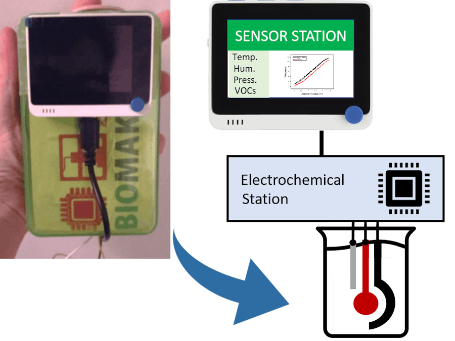
//The device shows 3 different displays depending on the value of the "m" variable, for observing the data, controlling the voltage, and changing the speed of the stripping voltammetry assay
//Each value of "m" is controlled by the push buttons and starts the different displays
if (m == 0){
//These function extract the environmental data from the BME680 sensors and store them into the variables that will be displayed on the LCD screen
Temp = bme680.sensor_result_value.temperature;
Hum = bme680.sensor_result_value.humidity;
Pres = bme680.sensor_result_value.pressure / 1000.0;
Gas = bme680.sensor_result_value.gas / 1000.0;
//Functions to display the data on the LCD
spr.fillSprite(TFT_WHITE);
spr.fillRect(0, 0, 320, 50, TFT_DARKGREEN);
spr.fillRect(0, 50, 150, 240, TFT_GREENYELLOW);
spr.setTextColor (TFT_WHITE);
spr.setTextSize (3);
spr.drawString ("SENSOR STATION", 40, 15);
spr.setTextColor (TFT_BLACK);
spr.setTextSize (2);
spr.drawString("T:",10,73);
spr.drawNumber(Temp, 40, 73);
spr.drawString("C",100,73);
spr.setTextSize (2);
spr.drawNumber(Hum, 40, 120);
spr.drawString("%",100,120);
spr.setTextSize (2);
spr.drawString("P:",10,167);
spr.drawNumber(Pres, 40, 167);
spr.drawString("hPa",100,167);
spr.setTextSize (2);
spr.drawString("G:",10,214);
spr.drawNumber(Gas, 40, 214);
spr.drawString("kOhm",100,214);
spr.setTextSize (1);
//Settings for the line graph title
auto header = text(187, 57)
.value("Stripping Voltammetry")
.width(9)
.height (4);
header.height(9);
header.draw();
if (w == 2){
spr.drawFastVLine(312,73,150,TFT_BLACK);
spr.drawFastVLine(223,215,5,TFT_BLACK);
spr.drawFastVLine(267,215,5,TFT_BLACK);
spr.drawFastHLine(179,73,133,TFT_BLACK);
//Function to calculate the Voltages displayed in the x axis. This function varies depending on whether the stripping voltammetry is increasing or decreasing
V5 = MCP1*1.2 - 9.4;
V6 = MCP2*1.2 - 9.4;
if (V5 < 0){
V5 = 0;
}
if (V6 < 0){
V6 = 0;
}
if (V2 >= V1){
p1 = ((V6-V5)/3) + V5;
p2 = (2*(V6-V5)/3) + V5;
spr.drawNumber(V5,174,223);
spr.drawNumber(p1,216,223);
spr.drawNumber(p2,260,223);
spr.drawNumber(V6,309,223);
}
if (V1 > V2){
p2 = ((V5-V6)/3) + V6;
p1 = (2*(V5-V6)/3) + V6;
spr.drawNumber(V6,174,223);
spr.drawNumber(p2,216,223);
spr.drawNumber(p1,260,223);
spr.drawNumber(V5,309,223);
}
//Function to display either the slope of the plot, the peak, or both. Takes the data from the 3rd display (push button 3)
// Calculating the slope
Sl = ((x1[y3-1]) - (x1[0]))/((MCP2)-(MCP1));
if (Sl < 0){
Sl = Sl*-100;
}
if (Sl > 0){
Sl = Sl*100;
}
//Calculating the peaks of the potentiometric assay
if (MCP1 >= MCP2){
for (c=1; c<y3; c++){
if (x1[c] < mx){
mx = x1[c];
}
}
}
if (MCP2 > MCP1){
for (c=1; c<y3; c++){
if (x1[c] > mx){
mx = x1[c];
}
}
}
//Function to display either the peak of the stripping voltammetry assay, the slope or both
if (M == 1){
spr.drawString("Slope:",180,90);
spr.drawNumber(Sl,215,90);
}
if (M == 2){
spr.drawString("Peak:",180,90);
spr.drawNumber(mx,210,90);
}
if (M == 3){
spr.drawString("Peak:",180,90);
spr.drawNumber(mx,210,90);
spr.drawString("Slope:",180,105);
spr.drawNumber(Sl,215,105);
}
//Settings for displaying the line graph
auto content = line_chart(152, 70); //(x,y) where the line graph begins
content
.height(160) //actual height of the line chart
.width(160) //actual width of the line chart
.based_on(x[0]) //Starting point of y-axis, must be a float
.show_circle(true) //drawing a cirle at each point, default is on.
.value(data) //passing through the data to line graph
.color(TFT_RED) //Setting the color for the line
.draw();
}
mx = 0;
}
//The second display is used to change the values of the voltage that will be used during thr stripping voltammetry assay
if (m == 1){
//These functions show the titles that appear on the screen
spr.fillSprite(TFT_BLACK);
spr.fillRect(0, 0, 320, 50, TFT_ORANGE);
spr.setTextColor (TFT_WHITE);
spr.drawString ("SELECT VOLTAGE", 40, 15);
spr.setTextSize (3);
spr.fillTriangle(67, 130, 130, 130, 97, 110, TFT_GREENYELLOW);
spr.fillTriangle(67, 190, 130, 190, 97, 210, TFT_GREENYELLOW);
spr.fillTriangle(201, 130, 264, 130, 231, 110, TFT_GREENYELLOW);
spr.fillTriangle(201, 190, 264, 190, 231, 210, TFT_GREENYELLOW);
spr.setTextSize (3);
spr.setTextColor (TFT_WHITE);
spr.drawString ("From:", 50, 65);
spr.setTextColor (TFT_WHITE);
spr.drawString ("To:", 214, 65);
//Function used to knw the position of the user's control respect to the screen values
if (digitalRead(WIO_5S_LEFT) == LOW) {
n = n - 1;
}
if (digitalRead(WIO_5S_RIGHT) == LOW) {
n = n + 1;
}
if (n < 1){
n = 6;
}
if (n > 6){
n = 1;
}
//The following functions detect what is the value that the user is currently modifying and shows it in yellow for a better visualization. Upon pushing the joysticks up or down, this value increases or decreases respectively
if (n == 1){
spr.setTextSize (3);
spr.setTextColor (TFT_YELLOW);
spr.drawNumber (L1, 60, 150);
spr.setTextColor (TFT_WHITE);
spr.drawNumber (L2, 85, 150);
spr.drawNumber (L3, 110, 150);
spr.drawNumber (U1, 219, 150);
spr.drawNumber (U2, 234, 150);
spr.drawNumber (U3, 259, 150);
if (digitalRead(WIO_5S_UP) == LOW) {
L1 = L1 + 1;
V1 = V1 + 100;
spr.fillTriangle(67, 130, 130, 130, 97, 110, TFT_RED);
}
if (digitalRead(WIO_5S_DOWN) == LOW) {
spr.fillTriangle(67, 190, 130, 190, 97, 210, TFT_RED);
L1 = L1 - 1;
V1 = V1 - 100;
}
}
if (n == 2){
spr.setTextSize (3);
spr.setTextColor (TFT_YELLOW);
spr.drawNumber (L2, 85, 150);
spr.setTextColor (TFT_WHITE);
spr.drawNumber (L1, 60, 150);
spr.drawNumber (L3, 110, 150);
spr.drawNumber (U1, 219, 150);
spr.drawNumber (U2, 234, 150);
spr.drawNumber (U3, 259, 150);
if (digitalRead(WIO_5S_UP) == LOW) {
spr.fillTriangle(67, 130, 130, 130, 97, 110, TFT_RED);
L2 = L2 + 1;
V1 = V1 + 10;
}
if (digitalRead(WIO_5S_DOWN) == LOW) {
spr.fillTriangle(67, 190, 130, 190, 97, 210, TFT_RED);
L2 = L2 - 1;
V1 = V1 - 10;
}
}
if (n == 3){
spr.setTextSize (3);
spr.setTextColor (TFT_YELLOW);
spr.drawNumber (L3, 110, 150);
spr.setTextColor (TFT_WHITE);
spr.drawNumber (L1, 60, 150);
spr.drawNumber (L2, 85, 150);
spr.drawNumber (U1, 219, 150);
spr.drawNumber (U2, 234, 150);
spr.drawNumber (U3, 259, 150);
if (digitalRead(WIO_5S_UP) == LOW) {
spr.fillTriangle(67, 130, 130, 130, 97, 110, TFT_RED);
V1 = V1 + 1;
L3 = L3 + 1;
}
if (digitalRead(WIO_5S_DOWN) == LOW) {
spr.fillTriangle(67, 190, 130, 190, 97, 210, TFT_RED);
V1 = V1 - 1;
L3 = L3 - 1;
}
}
if (n == 4){
spr.setTextSize (3);
spr.setTextColor (TFT_YELLOW);
spr.drawNumber (U1, 219, 150);
spr.setTextColor (TFT_WHITE);
spr.drawNumber (L1, 60, 150);
spr.drawNumber (L2, 85, 150);
spr.drawNumber (L3, 110, 150);
spr.drawNumber (U2, 234, 150);
spr.drawNumber (U3, 259, 150);
if (digitalRead(WIO_5S_UP) == LOW) {
spr.fillTriangle(201, 130, 264, 130, 231, 110, TFT_RED);
V2 = V2 + 100;
U1 = U1 + 1;
}
if (digitalRead(WIO_5S_DOWN) == LOW) {
V2 = V2 - 100;
U1 = U1 - 1;
}
}
if (n == 5){
spr.setTextSize (3);
spr.setTextColor (TFT_YELLOW);
spr.drawNumber (U2, 234, 150);
spr.setTextColor (TFT_WHITE);
spr.drawNumber (L1, 60, 150);
spr.drawNumber (L2, 85, 150);
spr.drawNumber (L3, 110, 150);
spr.drawNumber (U1, 219, 150);
spr.drawNumber (U3, 259, 150);
if (digitalRead(WIO_5S_UP) == LOW) {
spr.fillTriangle(201, 130, 264, 130, 231, 110, TFT_RED);
V2 = V2 + 10;
U2 = U2 + 1;
}
if (digitalRead(WIO_5S_DOWN) == LOW) {
spr.fillTriangle(201, 190, 264, 190, 231, 210, TFT_RED);
V2 = V2 - 10;
U2 = U2 - 1;
}
}
if (n == 6){
spr.setTextSize (3);
spr.setTextColor (TFT_YELLOW);
spr.drawNumber (U3, 264, 150);
spr.setTextColor (TFT_WHITE);
spr.drawNumber (L1, 50, 150);
spr.drawNumber (L2, 95, 150);
spr.drawNumber (L3, 115, 150);
spr.drawNumber (U1, 194, 150);
spr.drawNumber (U2, 239, 150);
if (digitalRead(WIO_5S_UP) == LOW) {
spr.fillTriangle(201, 130, 264, 130, 231, 110, TFT_RED);
V2 = V2 + 1;
U3 = U3 + 1;
}
if (digitalRead(WIO_5S_DOWN) == LOW) {
spr.fillTriangle(201, 190, 264, 190, 231, 210, TFT_RED);
V2 = V2 - 1;
U3 = U3 - 1;
}
}
// Setting up the number limits for the voltage. In this case, the maximum allowed voltage we set was 600 mV
if (U1<0){
U1 = 0;
V2 = V4;
}
if (U1>6){
U1 = 6;
V2 = V4;
}
if (L1<0){
L1 = 0;
V1 = V3;
}
if (L1>6){
L1 = 6;
V1 = V3;
}
if (U2<0){
U2 = 0;
V2 = V4;
}
if (U2>9){
U2 = 9;
V2 = V4;
}
if (L2<0){
L2 = 0;
V1 = V3;
}
if (L2>9){
L2 = 9;
V1 = V3;
}
if (U3<0){
U3 = 0;
V2 = V4;
}
if (U3>9){
U3 = 9;
V2 = V4;
}
if (L3<0){
L3 = 0;
V1 = V3;
}
if (L3>9){
L3 = 9;
V1 = V3;
}
V3 = V1;
V4 = V2;
}
//This section of the code shows the programme used in the display of the 3rd push button, which allows the control of the stripping voltammetry speed and to select the data that is displayed
if (m == 2){
//Similar to the case of the second display, the titles are defined, and only the ones that are being changed are shown in yellow, allowing the user to better select the conditions for their experiments with the joystick
spr.fillSprite(TFT_BLACK);
spr.fillRect(0, 0, 320, 50, TFT_BLUE);
spr.setTextColor (TFT_WHITE);
spr.drawString ("SWEEP PARAMETERS", 15, 15);
spr.setTextSize (3);
spr.fillTriangle(67, 130, 130, 130, 97, 110, TFT_GREENYELLOW);
spr.fillTriangle(67, 190, 130, 190, 97, 210, TFT_GREENYELLOW);
spr.fillTriangle(201, 130, 264, 130, 231, 110, TFT_GREENYELLOW);
spr.fillTriangle(201, 190, 264, 190, 231, 210, TFT_GREENYELLOW);
spr.setTextSize (3);
spr.setTextColor (TFT_WHITE);
spr.drawString ("Sp(mV/s)", 30, 65);
spr.setTextColor (TFT_WHITE);
spr.drawString ("Data:", 200, 65);
if (digitalRead(WIO_5S_LEFT) == LOW) {
n2 = n2 - 1;
}
if (digitalRead(WIO_5S_RIGHT) == LOW) {
n2 = n2 + 1;
}
if (n2 < 1){
n2 = 4;
}
if (n2 > 4){
n2 = 1;
}
if (M>3){
M = 1;
}
if (M<1){
M = 3;
}
//Similar to the previous cases, these functions determine where the titles are allocated, and changes the colour of the ones that are being used
if (n2 == 1){
spr.setTextSize (3);
spr.setTextColor (TFT_YELLOW);
spr.drawNumber (S1, 70, 150);
spr.setTextColor (TFT_WHITE);
spr.drawNumber (S2, 90, 150);
spr.drawNumber (S3, 110, 150);
if (M == 1){
spr.drawString ("Slope", 198, 150);
}
if (M == 2){
spr.drawString ("Peak", 198, 150);
}
if (M == 3){
spr.drawString ("Both", 198, 150);
}
if (digitalRead(WIO_5S_UP) == LOW) {
S1 = S1 + 1;
Sp = Sp + 100;
spr.fillTriangle(67, 130, 130, 130, 97, 110, TFT_RED);
}
if (digitalRead(WIO_5S_DOWN) == LOW) {
spr.fillTriangle(67, 190, 130, 190, 97, 210, TFT_RED);
S1 = S1 - 1;
Sp = Sp - 100;
}
}
if (n2 == 2){
spr.setTextSize (3);
spr.setTextColor (TFT_YELLOW);
spr.drawNumber (S2, 90, 150);
spr.setTextColor (TFT_WHITE);
spr.drawNumber (S1, 70, 150);
spr.drawNumber (S3, 110, 150);
if (M == 1){
spr.drawString ("Slope", 198, 150);
}
if (M == 2){
spr.drawString ("Peak", 198, 150);
}
if (M == 3){
spr.drawString ("Both", 198, 150);
}
if (digitalRead(WIO_5S_UP) == LOW) {
spr.fillTriangle(67, 130, 130, 130, 97, 110, TFT_RED);
S2 = S2 + 1;
Sp = Sp + 10;
}
if (digitalRead(WIO_5S_DOWN) == LOW) {
spr.fillTriangle(67, 190, 130, 190, 97, 210, TFT_RED);
S2 = S2 - 1;
Sp = Sp - 10;
}
}
if (n2 == 3){
spr.setTextSize (3);
spr.setTextColor (TFT_YELLOW);
spr.drawNumber (S3, 110, 150);
spr.setTextColor (TFT_WHITE);
spr.drawNumber (S1, 70, 150);
spr.drawNumber (S2, 90, 150);
if (M == 1){
spr.drawString ("Slope", 200, 150);
}
if (M == 2){
spr.drawString ("Peak", 200, 150);
}
if (M == 3){
spr.drawString ("Both", 200, 150);
}
if (digitalRead(WIO_5S_UP) == LOW) {
spr.fillTriangle(67, 130, 130, 130, 97, 110, TFT_RED);
S3 = S3 + 1;
Sp = Sp + 1;
}
if (digitalRead(WIO_5S_DOWN) == LOW) {
spr.fillTriangle(67, 190, 130, 190, 97, 210, TFT_RED);
S3 = S3 - 1;
Sp = Sp - 1;
}
}
if (n2 == 4){
spr.setTextSize (3);
spr.setTextColor (TFT_YELLOW);
if (M == 1){
spr.drawString ("Slope", 198, 150);
}
if (M == 2){
spr.drawString ("Peak", 198, 150);
}
if (M == 3){
spr.drawString ("Both", 198, 150);
}
spr.setTextColor (TFT_WHITE);
spr.drawNumber (S1, 70, 150);
spr.drawNumber (S2, 90, 150);
spr.drawNumber (S3, 110, 150);
if (digitalRead(WIO_5S_UP) == LOW) {
spr.fillTriangle(201, 130, 264, 130, 231, 110, TFT_RED);
M = M + 1;
}
if (digitalRead(WIO_5S_DOWN) == LOW) {
spr.fillTriangle(201, 190, 264, 190, 231, 210, TFT_RED);
M = M - 1;
}
//Setting limits for the M parameter
if (M>3){
M = 1;
}
if (M<1){
M = 3;
}
}
//Setting up the number limits that are displayed on the LCD screen
if (S1<0){
S1 = 0;
Sp = Sp2;
}
if (S1>9){
S1 = 9;
Sp = Sp2;
}
if (S2<0){
S2 = 0;
Sp = Sp2;
}
if (S2>9){
S2 = 9;
Sp = Sp2;
}
if (S3<0){
S3 = 0;
Sp = Sp2;
}
if (S3>9){
S3 = 9;
Sp = Sp2;
}
Sp2 = Sp;
}
spr.pushSprite(0, 0);
delay(100);
//Function used to generate the stripping voltammetry pulse. This function is triggered after pressing the central button on the Joystick incorporated int he Wio Terminal
if (m == 3){
spr.setTextSize (2);
spr.drawString("Generating",170, 120);
spr.drawString("Data...",170, 150);
MCP1 = V1*500/600;
MCP2 = V2*500/600;
r = 1200/Sp;
y = 0;
y3 = 0;
MCP3 = MCP1;
MCP4 = MCP2;
MCP5 = MCP1;
uint32_t counter = MCP3;
if (MCP1 >= MCP2){
while (MCP3 > MCP4)
{
dac.setVoltage(counter, false);
x1[y3] = analogRead (A2);
if (MCP3%10 == 0){
x[y] = x1[y3];
y++;
}
MCP3--;
counter--;
delay (r);
y3++;
}
}
//Functions to apply the desired voltage. The function changes whteher there is an increasing or decreasing voltage being applied, and sets a delay between the pulses according to the chosen speed
if (MCP1 < MCP2){
while (MCP3 < MCP4){
dac.setVoltage(counter, false);
x1[y3] = (analogRead (A2));
Serial.print (x1[y3]);
Serial.print ("\t");
Serial.println (counter);
//Since the data capacity of the plot in the display is limited, only 1/10 of the actual recorded data is shown on the plot. However, the programme stores all the values in case that further calculations are needed
if (MCP3%10 == 0){
x[y] = x1[y3];
y++;
}
MCP3++;
counter++;
delay (r);
y3++;
}
}
m = 0;
w = 2;
delay (100);
for (y2=0; y2 < y; y2++) {
Serial.println (x[y2]);
data.push(x[y2]); //Function to read variables and store in data
}
for (y2=0; y2 < data.size(); y2++) { //Function to empty the doubles variable that stores the potentiostat data that is displayed on the screen
data.pop();
}
}
//These are the functions that record whether any of the push buttons have been pressed and changes the display accordingly
if (digitalRead(WIO_KEY_C) == LOW) {
m = 0;
}
if (digitalRead(WIO_KEY_B) == LOW) {
m = 1;
}
if (digitalRead(WIO_KEY_A) == LOW) {
m = 2;
}
//This function resets the parameters for the stripping voltammetry eperiments, allowing the user to repeat the measurements
if (digitalRead(WIO_5S_PRESS) == LOW) {
w = 1;
memset(x, 0, sizeof(x));
y = 0;
y3 = 0;
m = 3;
MCP3 = 0;
MCP4 = 0;
}
}


_3u05Tpwasz.png?auto=compress%2Cformat&w=40&h=40&fit=fillmax&bg=fff&dpr=2)
Comments