

Hardware components | ||||||
 |
| × | 1 | |||
 |
| × | 1 | |||
Software apps and online services | ||||||
| ||||||
| ||||||
Some time ago, I was looking for an UART design in VHDL that was easy to follow, and surprisingly I couldn't find one. Maybe I didn't search well enough, but anyway, I though this would be a good starting point for my tech hobby blog. So, this is my first project, please welcome UART interface in VHDL for the Basys 3 board.
This design allows transmitting bits from the board to the computer terminal, and receiving bits from the terminal to the board. You can transmit data from the board to the terminal by pressing the push button on the board. Transmitting bits can be set by using the user switches, and receiving bits can be checked on the user LEDs.
UART Interface SummaryIf you are a complete beginner in UART, I advise you to have a look at this wiki page here.
As the UART interface is a serial interface, the transmitter sends the data bit by bit. At the same time, the receiver has to catch each bit and convert it into the parallel data. Another important feature of the standard is the baud rate which defines how many bits UART can transmit per second. The interface allows many different baud rates, but in this project I use 115200 baud.
Let's have a look at the time frame used in this project:
I have used the simplest version of UART, as outlined:
- start bit (‘0’)
- 8 data bits
- no parity bit
- one stop bit (‘1’)
Here is the project tree in Vivado:
UART_controller.vhd- the top file which connects the design to the outside worldbutton_debounce.vhd- connects the transmitting push button to the rest of the project and prevents multiple actuation per one pressUART.vhd- combines tx and rx files togetherUART_tx.vhd- contains all the transmitter logicUART_rx.vhd- contains all the receiver logicconstrains.xdc- contains the pins connections and the master clock frequencyUART_controller_tb.vhd- this is the testbench for the design
The main part of the project is located in the UART_tx.vhd and UART_rx.vhd files. These files and their logic will be discussed in detail in the next sections.
If you prefer to build a project and program the chip first, you can jump to the Create a Project section and play around with the board before reading the rest of the theoretical part.
TransmitterThe UART_tx.vhd is a transmitting module. Here is the block diagram:
Each blue block represents a process in the UART_tx.vhd file.
baud_rate_clk_generatorgenerates the UART baud rate clock by setting the baud_rate_clk signal when the counter counts BAUD_CLK_TICKS ticks of the master clock. The BAUD_CLK_TICKS constant reflects the ratio between the master clock and the baud rate.
tx_start_detectorworks on the master clock frequency and catches short (one clock cycle long) impulses in the tx_start signal and keeps it for the UART_tx_FSM. tx_start_detector is needed because the UART_tx_FSM works on the baud rate frequency, but the button_debounce module generates one master clock cycle long impulse per one button push. start_detected keeps the information that such event has occurred. The second purpose of tx_start_detector is to secure the transmitting data. stored_data keeps the transmitting data saved during the transmission.
data_index_counter is a simple counter from 0 to 7 working on the baud rate frequency. It is used to perform transformation between the parallel data (stored_data) and the serial output (tx_data_out). The data_index signal is used in UART_tx_FSM to go over the stored_data vector and send the bits one by one.
UART_tx_FSM represents a Finite State Machine which has four states (IDLE, START, DATA, STOP). Here is the state diagram of the UART_tx_FSM block:
The code of the UART_tx.vhd file:
library ieee;
use ieee.std_logic_1164.all;
use ieee.numeric_std.all;


entity UART_tx is

    generic(
        BAUD_CLK_TICKS: integer := 868); -- clk/baud_rate (100 000 000 / 115 200 = 868.0555)

    port(
        clk            : in  std_logic;
        reset          : in  std_logic;
        tx_start       : in  std_logic;
        tx_data_in     : in  std_logic_vector (7 downto 0);
        tx_data_out    : out std_logic
        );
end UART_tx;


architecture Behavioral of UART_tx is

    type tx_states_t is (IDLE, START, DATA, STOP);
    signal tx_state  : tx_states_t := IDLE;


    signal baud_rate_clk     : std_logic:= '0';

    signal data_index        : integer range 0 to 7 := 0;
    signal data_index_reset  : std_logic := '1';
    signal stored_data       : std_logic_vector(7 downto 0) := (others=>'0');

    signal start_detected    : std_logic := '0';
    signal start_reset       : std_logic := '0';

begin


-- The baud_rate_clk_generator process generates the UART baud rate clock by
-- setting the baud_rate_clk signal when the counter counts BAUD_CLK_TICKS
-- ticks of the master clk. The BAUD_CLK_TICKS constant is specified in
-- the package and reflects the ratio between the master clk and the baud rate.

    baud_rate_clk_generator: process(clk)
    variable baud_count: integer range 0 to (BAUD_CLK_TICKS - 1) := (BAUD_CLK_TICKS - 1);
    begin
        if rising_edge(clk) then
            if (reset = '1') then
                baud_rate_clk <= '0';
                baud_count := (BAUD_CLK_TICKS - 1);
            else
                if (baud_count = 0) then
                    baud_rate_clk <= '1';
                    baud_count := (BAUD_CLK_TICKS - 1);
                else
                    baud_rate_clk <= '0';
                    baud_count := baud_count - 1;
                end if;
            end if;
        end if;
    end process baud_rate_clk_generator;


-- The tx_start_detector process works on the master clk frequency and catches
-- short (one clk cycle long) impulses in the tx_start signal and keeps it for
-- the UART_tx_FSM. tx_start_detector is needed because the UART_tx_FSM works on
-- the baud rate frequency, but the button_debounce module generates one master clk
-- cycle long impulse per one button push. start_detected keeps the information that
-- such event has occurred.
-- The second purpose of tx_start_detector is to secure the transmitting data.
-- stored_data keeps the transmitting data saved during the transmission.

    tx_start_detector: process(clk)
    begin
        if rising_edge(clk) then
            if (reset ='1') or (start_reset = '1') then
                start_detected <= '0';
            else
                if (tx_start = '1') and (start_detected = '0') then
                    start_detected <= '1';
                    stored_data <= tx_data_in;
                end if;
            end if;
        end if;
    end process tx_start_detector;


-- The data_index_counter process is a simple counter from 0 to 7 working on the baud
-- rate frequency. It is used to perform transformation between the parallel
-- data (stored_data) and the serial output (tx_data_out).
-- The data_index signal is used in UART_tx_FSM to go over the stored_data vector
-- and send the bits one by one.

    data_index_counter: process(clk)
    begin
        if rising_edge(clk) then
            if (reset = '1') or (data_index_reset = '1') then
                data_index <= 0;
            elsif (baud_rate_clk = '1') then
                data_index <= data_index + 1;
            end if;
        end if;
    end process data_index_counter;


-- The UART_FSM_tx process represents a Finite State Machine which has
-- four states (IDLE, START, DATA, STOP). See inline comments for more details.

    UART_tx_FSM: process(clk)
    begin
        if rising_edge(clk) then
            if (reset = '1') then
                tx_state <= IDLE;
                data_index_reset <= '1';   -- keep data_index_counter on hold
                start_reset <= '1';        -- keep tx_start_detector on hold
                tx_data_out <= '1';        -- keep tx line set along the standard
            else
                if (baud_rate_clk = '1') then   -- the FSM works on the baud rate frequency
                    case tx_state is

                        when IDLE =>

                            data_index_reset <= '1';    -- keep data_index_counter on hold
                            start_reset <= '0';         -- enable tx_start_detector to wait for starting impulses
                            tx_data_out <= '1';         -- keep tx line set along the standard

                            if (start_detected = '1') then
                                tx_state <= START;
                            end if;

                        when START =>

                            data_index_reset <= '0';   -- enable data_index_counter for DATA state
                            tx_data_out <= '0';        -- send '0' as a start bit

                            tx_state <= DATA;

                        when DATA =>

                            tx_data_out <= stored_data(data_index);   -- send one bit per one baud clock cycle 8 times

                            if (data_index = 7) then
                                data_index_reset <= '1';              -- disable data_index_counter when it has reached 8
                                tx_state <= STOP;
                            end if;

                        when STOP =>

                            tx_data_out <= '1';     -- send '1' as a stop bit
                            start_reset <= '1';     -- prepare tx_start_detector to be ready detecting the next impuls in IDLE

                            tx_state <= IDLE;

                        when others =>
                            tx_state <= IDLE;
                    end case;
                end if;
            end if;
        end if;
    end process UART_tx_FSM;


end Behavioral;The UART_rx.vhd is a receiving module. Here is the block diagram:
In contrast to UART_tx, here, I have built-in the counters inside the FSM (via the variables in the process, see the code). I did it just to demonstrate the different approaches while creating a FSM with counters. The first way (tx) is faster in hardware, but the second one is easier to implement in VHDL.
baud_rate_x16_clk_generator generates an over-sampled clock. The baud_rate_x16_clk signal is 16 times faster than the baud rate clock. Oversampling is needed to put the capture point at the middle of duration of the receiving bit. The BAUD_X16_CLK_TICKS constant reflects the ratio between the master clock and the x16 baud rate.
UART_rx_FSM represents a Finite State Machine which has four states (IDLE, START, DATA, STOP). Here is the state diagram of the UART_rx_FSM block:
The bit duration counter works on baud_rate_x16_clk
Here is the code of the UART_rx.vhd file:
library ieee;
use ieee.std_logic_1164.all;
use ieee.numeric_std.all;


entity UART_rx is

    generic(
        BAUD_X16_CLK_TICKS: integer := 54); -- (clk / baud_rate) / 16 => (100 000 000 / 115 200) / 16 = 54.25

    port(
        clk            : in  std_logic;
        reset          : in  std_logic;
        rx_data_in     : in  std_logic;
        rx_data_out    : out std_logic_vector (7 downto 0)
        );
end UART_rx;


architecture Behavioral of UART_rx is

    type rx_states_t is (IDLE, START, DATA, STOP);
    signal rx_state: rx_states_t := IDLE;

    signal baud_rate_x16_clk  : std_logic := '0';
    signal rx_stored_data     : std_logic_vector(7 downto 0) := (others => '0');


begin


-- The baud_rate_x16_clk_generator process generates an oversampled clock.
-- The baud_rate_x16_clk signal is 16 times faster than the baud rate clock.
-- Oversampling is needed to put the capture point at the middle of duration of
-- the receiving bit.
-- The BAUD_X16_CLK_TICKS constant reflects the ratio between the master clk
-- and the x16 baud rate.

    baud_rate_x16_clk_generator: process(clk)
    variable baud_x16_count: integer range 0 to (BAUD_X16_CLK_TICKS - 1) := (BAUD_X16_CLK_TICKS - 1);
    begin
        if rising_edge(clk) then
            if (reset = '1') then
                baud_rate_x16_clk <= '0';
                baud_x16_count := (BAUD_X16_CLK_TICKS - 1);
            else
                if (baud_x16_count = 0) then
                    baud_rate_x16_clk <= '1';
                    baud_x16_count := (BAUD_X16_CLK_TICKS - 1);
                else
                    baud_rate_x16_clk <= '0';
                    baud_x16_count := baud_x16_count - 1;
                end if;
            end if;
        end if;
    end process baud_rate_x16_clk_generator;


-- The UART_rx_FSM process represents a Finite State Machine which has
-- four states (IDLE, START, DATA, STOP). See inline comments for more details.

    UART_rx_FSM: process(clk)
        variable bit_duration_count : integer range 0 to 15 := 0;
        variable bit_count          : integer range 0 to 7  := 0;
    begin
        if rising_edge(clk) then
            if (reset = '1') then
                rx_state <= IDLE;
                rx_stored_data <= (others => '0');
                rx_data_out <= (others => '0');
                bit_duration_count := 0;
                bit_count := 0;
            else
                if (baud_rate_x16_clk = '1') then     -- the FSM works 16 times faster the baud rate frequency
                    case rx_state is

                        when IDLE =>

                            rx_stored_data <= (others => '0');    -- clean the received data register
                            bit_duration_count := 0;              -- reset counters
                            bit_count := 0;

                            if (rx_data_in = '0') then             -- if the start bit received
                                rx_state <= START;                 -- transit to the START state
                            end if;

                        when START =>

                            if (rx_data_in = '0') then             -- verify that the start bit is preset
                                if (bit_duration_count = 7) then   -- wait a half of the baud rate cycle
                                    rx_state <= DATA;              -- (it puts the capture point at the middle of duration of the receiving bit)
                                    bit_duration_count := 0;
                                else
                                    bit_duration_count := bit_duration_count + 1;
                                end if;
                            else
                                rx_state <= IDLE;                  -- the start bit is not preset (false alarm)
                            end if;

                        when DATA =>

                            if (bit_duration_count = 15) then                -- wait for "one" baud rate cycle (not strictly one, about one)
                                rx_stored_data(bit_count) <= rx_data_in;     -- fill in the receiving register one received bit.
                                bit_duration_count := 0;
                                if (bit_count = 7) then                      -- when all 8 bit received, go to the STOP state
                                    rx_state <= STOP;
                                    bit_duration_count := 0;
                                else
                                    bit_count := bit_count + 1;
                                end if;
                            else
                                bit_duration_count := bit_duration_count + 1;
                            end if;

                        when STOP =>

                            if (bit_duration_count = 15) then      -- wait for "one" baud rate cycle
                                rx_data_out <= rx_stored_data;     -- transer the received data to the outside world
                                rx_state <= IDLE;
                            else
                                bit_duration_count := bit_duration_count + 1;
                            end if;

                        when others =>
                            rx_state <= IDLE;
                    end case;
                end if;
            end if;
        end if;
    end process UART_rx_FSM;

end Behavioral;In order to send a bit from the Basys 3 board to the computer terminal we need to set the board switches and press the push button. At this moment we need to make sure that we send the bit ones. To do so, the button_debounce.vhd file comes.
Here is the block diagram of the module:
The flipflop_1 and flipflop_2 signal are different if the button_in input changes. The difference triggers pause_counter which passes the button_in signal farther from flip-flop 2 to flip-flop 3, but after COUNTER_SIZE master clock cycles. This allows the button_in signal to stabilise in a certain state before being passed.
The flipflop_3 and flipflop_4 signal has one master clock cycle delay. The delay is needed to create one short (one master clock cycle long) impuls at the button_out output. When pause_counter has finished, the flipflop_3 signal gets the button_in information. At that moment flipflop_4 hasn't changed yet. This creates '1' at the button_out output for one master clock cycle, only if flipflop_3 is '1' (the button has been pressed, not released).
Here is the code of the module:
library ieee;
use ieee.std_logic_1164.all;
use ieee.numeric_std.all;


entity button_debounce is
    generic (
            COUNTER_SIZE : integer := 10_000
            );
    port ( clk        : in  std_logic;
           reset      : in  std_logic;
           button_in  : in  std_logic;
           button_out : out std_logic);
end button_debounce;


architecture Behavioral of button_debounce is

    signal flipflop_1       : std_logic := '0';     -- output of flip-flop 1
    signal flipflop_2       : std_logic := '0';     -- output of flip-flop 2
    signal flipflop_3       : std_logic := '0';     -- output of flip-flop 3
    signal flipflop_4       : std_logic := '0';     -- output of flip-flop 4
    signal count_start      : std_logic := '0';

begin

-- The input_flipflops process creates two serial flip-flops (flip-flop 1 and
-- flip-flop 2). The signal from button_in passes them one by one. If flip_flop_1
-- and flip_flop_2 are different, it means the button has been activated, and
-- count_start becomes '1' for one master clock cycle.

    input_flipflops: process(clk)
    begin
        if rising_edge(clk) then
            if (reset = '1') then
                flipflop_1 <= '0';
                flipflop_2 <= '0';
            else
                flipflop_1 <= button_in;
                flipflop_2 <= flipflop_1;
            end if;
        end if;
    end process input_flipflops;


-- The count_start signal triggers the pause_counter process to start counting

    count_start <= flipflop_1 xor flipflop_2;


-- The pause_counter process passes the button_in signal farther from flip-flop 2
-- to flip-flop 3, but after COUNTER_SIZE master clock cycles. This allows
-- the button_in signal to stabilize in a certain state before being passed to the output.

    pause_counter: process(clk)
        variable count: integer range 0 to COUNTER_SIZE := 0;
    begin
        if rising_edge(clk) then
            if (reset = '1') then
                count := 0;
                flipflop_3 <= '0';
            else
                if (count_start = '1') then
                    count := 0;
                elsif (count < COUNTER_SIZE) then
                    count := count + 1;
                else
                    flipflop_3 <= flipflop_2;
                end if;
            end if;
        end if;
    end process pause_counter;


-- the purpose of the output_flipflop process is creating another flip-flop (flip-flop 4),
-- which creates a delay between the flipflop_3 and flipflop_4 signals. The delay is
-- one master clock cycle long.

    output_flipflop: process(clk)
    begin
        if rising_edge(clk) then
            if (reset = '1') then
                flipflop_4 <= '0';
            else
                flipflop_4 <= flipflop_3;
            end if;
        end if;
    end process output_flipflop;


-- The delay is needed to create one short (one master clock cycle long) impuls
-- at the button_out output. When pause_counter has finished, the flipflop_3 signal gets
-- the button_in information. At the moment flipflop_4 hasn't changed yet.
-- This creates '1' at the button_out output for one master clock cycle, only if
-- flipflop_3 is '1' (The button has been pressed, not released).

    with flipflop_3 select
    button_out <= flipflop_3 xor flipflop_4 when '1',
                  '0'                       when others;


end Behavioral;Before get started, make sure you have the board files in the Vivado folder. To do so, follow this guide.
Also, if you want to create the project step by step, you need to download the 8 project files from the Code section.
If you do not want to create the project step by step, you can download the completed project from the GitHub repo (Code section) and jump into the Design Simulation section.
Creating the project step by step:
Step 1 - open Vivado and click "Create Project"
Step 2 - name the project
Step 3 - choose "RTL Project" and leave the tick, we will add the files later
Step 4 - choose the board
Click Finish
You will see the empty project.
Step 5 - Click "+" to add the source files
Choose "Add or create design sources"
Click "Add Files"
Select 5 files as shown
Click "Finish"
Step 6 - repeat step 5 with "Add or create constraints" and the constraints.xdc file.
Step 7 - repeat step 5 with "Add or create simulation sources" and the UART_controller_tb.vhd and UART_controller_tb_behav.wcfg files.
Ones you have finished these steps you should see this:
In order to start the simulation you need to go this path:
Flow Navigator => SIMULATION => Run Simulation => Run Behavioral Simulation
In the simulation window, you need to set the simulation time as shown at the picture and click the "run" button with the (T) sub-sign.
You should be able to see the results of the simulation as in the image below. You can play with settings and select additional signals to understand the design better.
Once you finish playing with the simulation, you may want to build the project. To do so, you need to follow this path:
Flow Navigator => SYNTHESIS => Run Synthesis
You will see this window, click OK.
When the synthesis is complete, you can start the implementation right from this window:
The same way you can generate the bitstream:
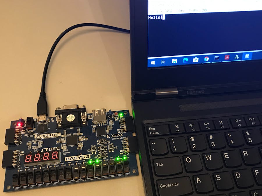
When the bitstream is ready, you need to connect the Basys3 board to our computer via a USB cable and turn the board on. After that, you need to open the Hardware Manager:
Click "Open Target" and choose "Auto Connect".
Right click on the part number and choose "Program Device".
You will see the window below, just click "Program".
The chip has to be programmed. The last step is setting up the computer terminal.
Tera Term SetupOpen Tera Term and choose "Serial" (in my case it is COM4, but it could be any port number) and click OK.
Go to Setup => Serial port... You will see this window, setup it as shown
Go to Setup => Terminal... and tick "Local echo", it allows you to see what you are typing.
Done!
How to PlayIn order to see the binary representation of the key you have pressed on your keyboard, you need to check the first 8 LEDs on the board.
To send a byte to the terminal you need to set the byte using the first 8 switches and press the central button (U18). You will see the ASCII representation of the byte you have set on the board.
To reset the design you need to press the top button (T18).
ConclusionThis project is far from a finished professional project since it does not have many important components such as: checking the stop bits, the parity bit, meta stability preventing, buffers at the pins, etc. I wanted to focus on the main design: the logic of the transmitter and receiver.
I hope the project is helpful and useful.


Comments