

Hardware components | ||||||
 |
| × | 1 | |||
| × | 1 | ||||
 |
| × | 1 | |||
 |
| × | 1 | |||
| × | 1 | ||||
| × | 1 | ||||
| × | 1 | ||||
| × | 1 | ||||
| × | 1 | ||||
| × | 1 | ||||
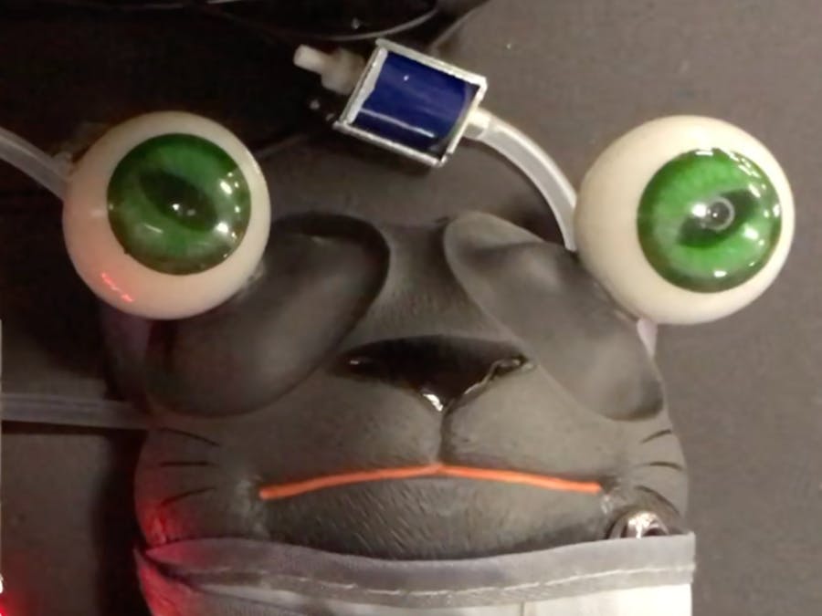
During the pandemic, the opportunity to work from home has naturally provided many people a separate space to cope with work-related stress. As people transition back to working in the office, there is a need for a light-hearted way of indicating that you still need your individual space during stressful times. The Stress Buddy sits on your desk, and with the push of a button, a stress toy is squeezed to visually communicate that your stress is nearing an eye-popping level.
Overview:The Stress Buddy relies on a system of tubing to pump air from the surrounding environment into a blood pressure cuff, which squeezes the stress toy as the cuff inflates. Positive pressure is generated through the use of an electric air pump and the cuff is depressurized through the use of a solenoid valve. Throughout inflation and deflation, air pressure readings are obtained through an analog air pressure sensor, which are then correlated with light hearted messages indicating stress levels shown on a 4-digit 7-segment display.
If the user is feeling stressed, they will push a button and the compression of the stress toy will begin. When the facial expression of the toy and the message on the screen matches the user's stress level, they would push the button again to freeze the toy and display. A third press of the button decompresses the toy and returns the Stress Buddy to its original state.
Electronic Hardware:In addition to a PocketBeagle board for programming, there are four main electric hardware components of the Stress Buddy: 1) a DC 3V Micro Vacuum Air Pump, 2) a Normally-Closed Solenoid Valve, 3) a 0-1 PSI Analog Pressure Sensor, and 4) a 4-Digit 7-Segment Display. The PocketBeagle is connected to a generic breadboard through the soldering of male to female header pins. Note here that P1_5 and P1_7, P1_13 and P1_15 are soldered together to enable USB host port functionality. Jumper wires are used to connect the pins of the PocketBeagle to various electrical components on the breadboard. Two analog input pins are connected to the pressure sensor, reading the V_supply and V_out of the sensor. GPIO pins and transistors control both the air pump and solenoid valve, connected to 3.3V and 5V power rails respectively. Finally, the display is controlled and connected to I2C pins.
A summary of connections for each main electrical hardware component as well as a fritzing diagram can be found below.
Air Pump Connections:
- + --> 3.3V (rail)
- - --> NPN Transistor Collector
Solenoid Valve Connections:
- + --> 5V (VOUT)
- - --> NPN Transistor Collector (here a ULN2803A transistor array is used)
Pressure Sensor Connections:
- V_out --> AIN5 3.3V (P2_35)
- V_supply --> 3.3V (rail)
- GND --> GND (rail)
Display Connections:
- + --> 3.3V (rail)
- - --> GND (rail)
- D --> I2C1_SDA (P2_11)
- C --> I2C1_SCL (P2_9)
The assembly of non-electrical components for the Stress Buddy begins with the the stress toy and blood pressure cuff. First, the toy is inserted into the blood pressure cuff and the strap is pulled tight with only the head of the toy protruding from the cuff. The cuff is then rolled around the toy. Because the length of velcro does not extend far enough to secure the roll around the toy, velcro straps are then secured around the toy to prevent unraveling during inflation.
Once the stress toy has been rolled inside the blood pressure cuff, the silicone tubing can be cut and attached. It is best to first assemble all electrical components on the breadboard and estimate the length of tubing required to reach every components position prior to cutting. When attaching the tubing to the port of the blood pressure cuff, the silicone will need to be stretched around the port to provide a secure fit. Two Y-connectors can then be inserted to allow for branching of the tubing and attachment of the air pump, solenoid valve, and pressure sensor.
To eventually make the device independent from an external computer, it is important to make sure that the code is able to autoboot on upon powering on the PocketBeagle. In order to accomplish this, follow the instructions here: https://phoenixnap.com/kb/crontab-reboot
Lessons Learned:- The code used in this project calculates pressure readings based on the output voltage from the analog pressure sensor. While the pure voltage outputs could be used to trigger the messages displayed, pressure measurements were calculated with the eventual goal of applying this hardware for detecting the air pressure of an inflatable bladder (think blood pressure monitor). The equation used for this calculation can be found in the pressure sensor's datasheet.
- It is important to note that the solenoid valves used in this device are designated as "normally-closed." This means that in the unpowered state the valve is closed, and in the powered state it will open. Thus, a GPIO pin set to high corresponds to open and a low setting corresponds to closed.
To build upon this design, one could explore any of the following future directions:
- The use of a pressure sensor with a larger pressure range. Currently, the pressure sensor only senses air pressures between 0-1PSI. However, 1PSI is insufficient to produce the full eye-popping behavior on the squeeze toy.
- Currently, the air pump takes about a minute to produce the pressure required pop the eyes of the stress toy. In the future, an air pump with a higher flow rate could be used to decrease this time.
- A potentiometer could be implemented as an alternative means of controlling inflation. The user could turn the knob, and then the device could inflate to the desired level.
- The ULN2803AN could be replaced by a single transistor, but was used due to a lack of available components.
- All components could be integrated into a singular housing and a battery pack could be purchased to remove the requirement for an external power source.


Comments