


Hardware components | ||||||
_ztBMuBhMHo.jpg?auto=compress%2Cformat&w=48&h=48&fit=fill&bg=ffffff) |
| × | 1 | |||
 |
| × | 1 | |||
| × | 1 | ||||
 |
| × | 2 | |||
 |
| × | 1 | |||
 |
| × | 1 | |||
 |
| × | 1 | |||
Software apps and online services | ||||||
 |
| |||||
Hand tools and fabrication machines | ||||||
 |
| |||||
In this intermediate-level electronics and radio communication tutorial, we’ll dive into building a fully functional 8+ channel RC (radio control) transmitter and receiver using the Arduino platform and the nRF24L01+ wireless module. This project combines core skills in microcontroller programming, sensor integration, and RF communication, and is perfect for hobbyists looking to expand their knowledge of DIY remote control systems.
ApplicationsThis RC system can be used in:
- RC planes, boats, and cars
- DIY drones or quadcopters
- Wireless robotics control
- Multi-servo control systems
- 📡 2.4 GHz RF Communication: It operates in the 2.4 GHz ISM band for wireless data transmission over short to medium ranges (1km - 5km with external antennae).
- 📦 Packet-Based Communication: Data is sent in small packets (up to 32 bytes), with built-in CRC checks for errors and automatic acknowledgments (ACKs) for reliability.
- 🔄 Multiple Data Pipes: Supports up to 6 data pipes, allowing one receiver to listen to multiple transmitters using unique addresses.
- ⚡ Low Power Consumption: Consumes only ~12 mA when transmitting and can enter ultra-low-power sleep modes for battery efficiency.
- 🔧 SPI Interface: Communicates with microcontrollers using the SPI protocol for high-speed data transfer and configuration.
- 📶 Adjustable Power & Data Rates: Transmission power and data rate (250 kbps, 1 Mbps, 2 Mbps) can be tuned for range vs. speed trade-offs.
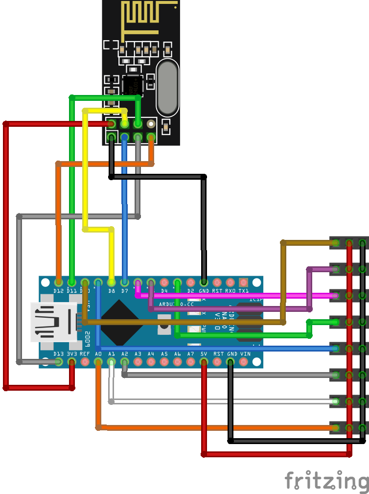
Note: To power the receiver, use only 1 (ONE) ESC's BEC as more than 1 power input can fry the nano's 5v pin.Radio Summary
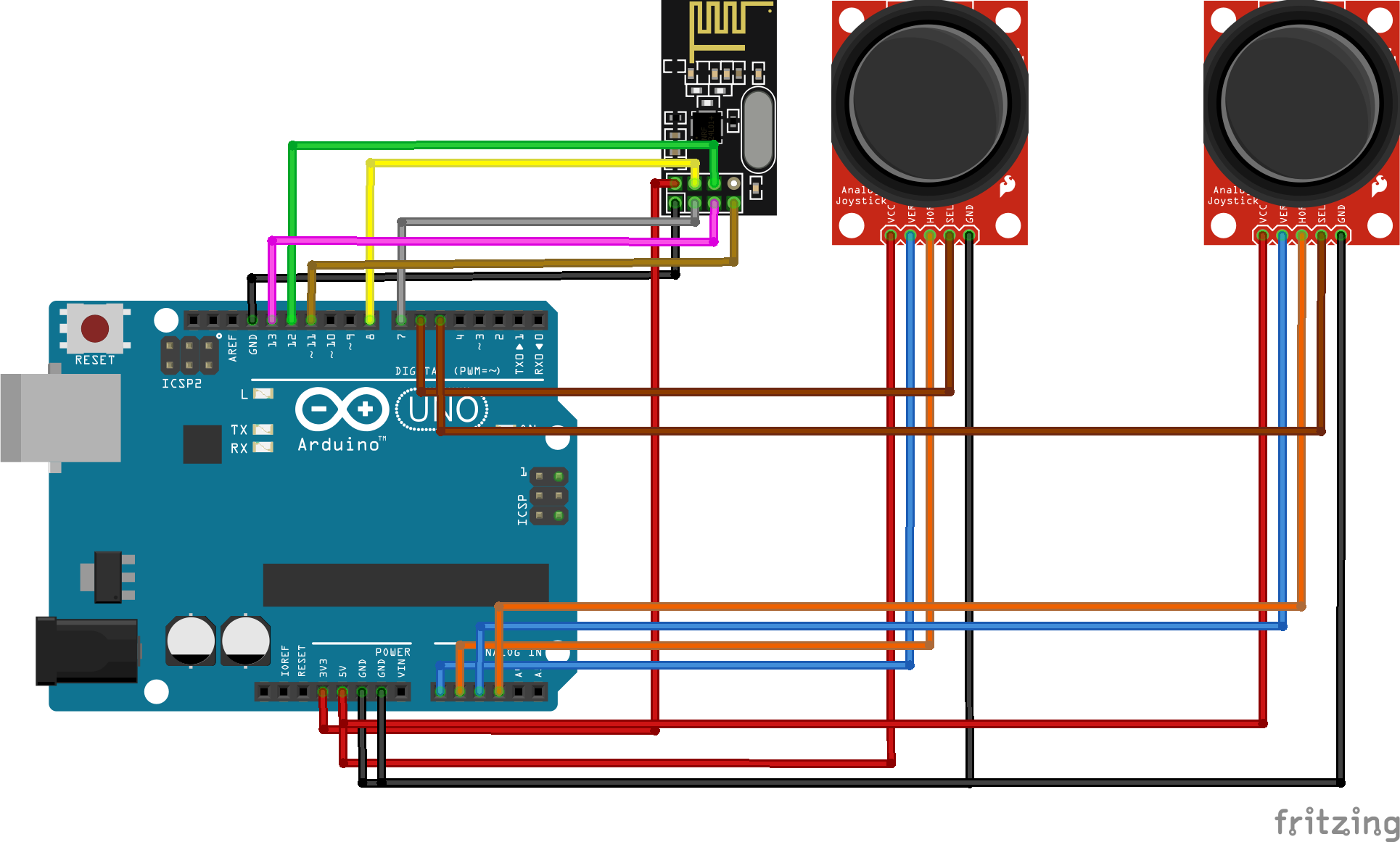
Transmitter Side:
- Reads analog or digital values from input devices like potentiometers and switches.
- Packs these values into a structured data packet.
- Sends the packet via the nRF24L01+ module at a set frequency.
Receiver Side:
- Continuously listens for incoming packets.
- Parses the received data and maps it to servo positions or motor speeds.
- Includes safety features like timeout detection for signal loss.
Main Functionality ✅:
- Creates a wireless RC transmitter using potentiometers (or joysticks) and buttons.
- Send control data over nRF24L01+ to a receiver to control:
- 4 analog channels: aileron, elevator, rudder, and throttle
- 2 digital channels: buttons (e.g., for eject or gear)
- Apply exponential response curves (expo) to the analog controls for smoother stick control near center.
🔧 Libraries and Initialization
#include <SPI.h>
#include <nRF24L01.h>
#include <RF24.h>- These libraries allow the Arduino to use SPI and communicate with the nRF24L01+ radio.
RF24 radio(7, 8); // CE, CSN
const byte address[6] = "77777";- Sets up the radio object, with CE on pin 7 and CSN on pin 8.
- Uses a 5-character pipe address for communication with the receiver.
📦 Data Structure (package)
struct package {
    int x1 = 0; // aileron
    int y1 = 0; // elevator
    int x2 = 0; // rudder
    int y2 = 0; // thrust
    char b1 = '0'; // eject button 1
    char b2 = '0'; // eject button 2
};
struct package data;- This is a compact custom protocol taking only 18 bytes.
- It transfers 4 analog axis positions + 2 button states efficiently in a single packet.
- Creates a global instance named data.
Note: You can add more variables but only up to 32 bytes (int is 4 bytes, char is 1 byte and etc.).
🛠️ Setup Function
Serial.begin(9600);
radio.begin();
radio.openWritingPipe(address);
radio.setPALevel(RF24_PA_MIN);
radio.setDataRate(RF24_250KBPS);
radio.setAutoAck(false);
radio.stopListening();- Serial.begin(9600): Enables serial debugging.
- radio.begin(): Initializes the nRF24L01+ module.
- openWritingPipe(): Sets the address used to send data to the receiver.
- setPALevel(): Lowers the power level (use RF24_PA_LOW or HIGH for more range).
- setDataRate(): Uses a slow and reliable data rate (250 kbps).
- stopListening(): Sets the module to transmit mode.
Note: Use the exact same settings for the receiver and transmitter.
🔁 Main Loop
data.x1 = applyExpo(map(analogRead(A1), 0, 1023, 0, 180), 0.4); // Aileron
data.y1 = applyExpo(map(analogRead(A0), 0, 1023, 0, 180), 0.5); // Elevator
data.x2 = applyExpo(map(analogRead(A3), 0, 1023, 0, 180), 0.3); // Rudder
data.y2 = map(analogRead(A2), 0, 1023, 0, 180); // Throttle- Reads joystick values from analog pins.
- Converts analog values (0–1023) to servo angles (0–180).
- Applies exponential curves using the applyExpo() function to aileron, elevator, and rudder.
data.b1 = digitalRead(button1Pin) ? '1' : '0';
data.b2 = digitalRead(button2Pin) ? '1' : '0';- Reads button states (HIGH = not pressed).
- Sends '1' if not pressed, '0' if pressed (you may want to flip this logic if needed).
radio.write(&data, sizeof(data));- Sends the entire data packet over the radio to the receiver.
📈 applyExpo() Function
int applyExpo(int input, float expo) {
    float normalized = (input - 90) / 90.0;
    float curved = normalized * (1 - expo) + pow(normalized, 3) * expo;
    return constrain((curved * 90) + 90, 0, 180);
}- This function applies an exponential response curve to the input:
- expo = 0: full linear response (no curve).
- expo > 0: softens sensitivity near the center.
- It maps input in the 0–180 range to a normalized curve around 90 (center).
Note: This gives you precise control near the center of the joystick and full travel at the ends.Receiver Code
Main Functionality ✅:
- Receives control signals wirelessly from a transmitter using the nRF24L01+ module.
- Parses 6 channels (can be expanded) of input: 4 analog (x1, y1, x2, y2) and 2 digital (b1, b2).
- Drives 5 servos for 2 ailerons, 1 elevator, 1 rudder, and 1 motor (ESC with BEC).
- Applies trimming, mapping, expo (via dualRate), and signal safety (e.g., constrain()).
📡 nRF24L01 Setup
radio.begin();
radio.openReadingPipe(0, address);
radio.setPALevel(RF24_PA_MIN);
radio.setDataRate(RF24_250KBPS);
radio.setAutoAck(false);
radio.startListening();- Uses pipe 0 with address "77777" to listen for incoming data.
- Set to minimum power (consider RF24_PA_LOW or RF24_PA_HIGH for better range).
- Uses 250 kbps for better reliability over longer distances.
- Disables auto acknowledgment for minimal latency or ping.
Note: To expand range, consider making an nrf24lo1, ground range booster (link here).
🕹️ Servo Initialization
motor.attach(10, 1000, 2000); // ESC or throttle servo
rudder.attach(9);
elevator.attach(6);
aileron1.attach(5);
aileron2.attach(3);- Custom PWM range (1000–2000 µs) for throttle via attach(pin, min, max) — used for ESCs.
- Other servos use default 544–2400 µs range.
🎮 Control Logic
motor.write(map(data.y2, 90, 180, 0, 90*0.7));- Throttle starts at 90 (0 thrust) as it is the joystick's neutral or default position.
- 0.7 is used as a limiter so the motor doesn't get too hot or burnout.
rudder.write(constrain(map(data.x2, ...) + trimRudder, 0, 180));
aileron1.write(constrain(map(data.x1, ...) + trimAileron1, 0, 180));
aileron2.write(constrain(map(data.x1, ...) + trimAileron2, 0, 180));
elevator.write(constrain(map(data.y1, ...) + trimElevator, 0, 180));- Uses dualRate() to limit travel based on a rate factor (for beginner flyers).
- Applies trim values to all surfaces.
- Elevator mapping is inverted, which is typical depending on joystick orientation.
🧮 Dual Rate Function
int dualRate(int maxDeflection, float percentRate) {
    return percentRate * maxDeflection;
}- Limits movement range.
- Clean and reusable for all surfaces.


12 projects • 14 followers
Electrical Engineering Undergrad Student specialized in low-level programming, IoT projects, and microcontroller electronics.


Comments