

Hardware components | ||||||
 |
| × | 1 | |||
| × | 1 | ||||
 |
| × | 1 | |||
 |
| × | 2 | |||
 |
| × | 1 | |||
 |
| × | 1 | |||
 |
| × | 1 | |||
| × | 1 | ||||
Software apps and online services | ||||||
 |
| |||||
Hand tools and fabrication machines | ||||||
 |
| |||||
 |
| |||||
 |
| |||||
The modern factory process relies heavily on digital technology to monitor different parts of the facility. With digital technology, factories have become safer, more productive and easier to operate. This technology is taken for granted which becomes evident when you visit older and older factories. I work at an 18th century grist mill where electricity is scarcely used. Flat belts and pulleys transmit power from line shafts to machinery, and the majority of our machinery is made of wood, cut by hand and assembled in the early 1900s. When I was asked to develop a network of sensors to monitor the different parts of my job's factory process, I jumped at the opportunity to bring my workplace into the 21st century.
The mill can be thought of as one big machine with many smaller processes happening simultaneously. Therefore, we needed a variety of sensors that can oversee these processes and alert us when something isn't working the way it should. The initial sensors included at the project's launch take measurements inside a grain bin to figure out how full it is, monitor the 0-10v dc output of an AC Tech SMVector controller, and take temperature and humidity readings of various parts of the building. Future sensors will include spout flow meters that measure the grain flowing through a spout, magnetic switches on 2 way valves that record which spouting the grain moves through, and temperature sensors on line shaft bearings that let us know how hot a bearing has become.
With the introduction of this network, we can save time by not walking around visually inspecting the processes throughout the four floors of the building and we can quantify parts of different processes to give us data for statistical purposes .
The network consists of the standard nodes, Arduino powered devices connected to sensors, the base node, the Arduino device that acts as the network hub, and a Raspberry Pi, the device that acts as the server and data interpreter.
The nRF24L01 (RF24) module is a radio frequency transmitter that is capable of sending and receiving data to other RF24 modules. The RF24 modules can be hooked up to an Arduino Nano by following the the wiring diagram below.
RF24 modules can be powered at 5 volts but its recommended that you power it at 3.3 volts. To ensure the RF24 module doesnt lose power sporadically, a decoupling capacitor is required. I used a 10 uF electrolytic capacitor as close to the RF module's power and ground pins (not shown in diagram). Without this capacitor, the RF module will perform poorly.
Once I had an understanding of the RF24 module, it was time to make a PCB that could be customized to allow for different sensors.
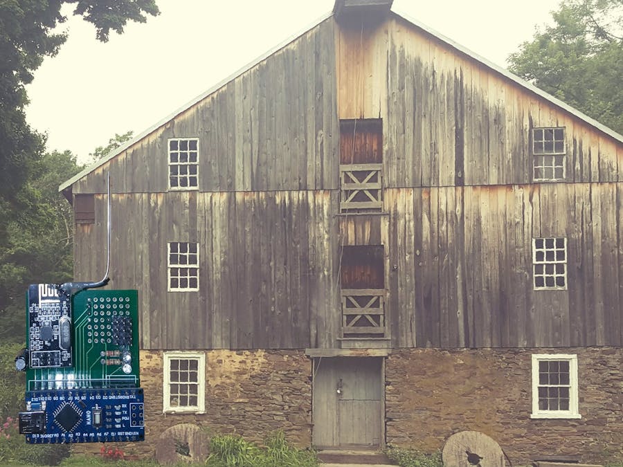
The PCB I designed consists of an Arduino Nano, an RF24 module, a 10 uF electrolytic capacitor, 2 indicator LEDs, two resistors for the LEDs, and a spot to put a micro usb female connector to power the node. When a node is put together, it looks like this...
Each node is then encased in a 3D-printed case that makes it easy to mount to walls and surfaces.
Due to range issues, I have modified the RF24 to add a longer antenna. The antenna modification boosts the range of a stock RF24 Module from a 5-10 foot range to 20 or 30 feet. To modify the RF24 antenna, I cut a piece of solid 18 gauge wire to about 7 inches and soldered it onto the end of the trace for the RF24 antenna. WARNING: Extending the RF24 antenna can pull up the pre-existing trace on the RF24 module if too much pressure is applied to the antenna.
I put a large glob of hot glue onto both sides of the new antenna because, during experimentation, I found that it helps stiffen the new antenna to the RF24 module.
To bring the system together, each network needs a base node where all the data is routed to. In my project, I use a node connected to a Raspberry Pi over serial cable. The node is used to send and receive network messages and the RPI is used as the central server for recording and interpreting data (the server program is explained later in this project).
For this project, I exclusively used the RF24Network library (created by Tmrh20) to handle the RF24 messaging. The RF24Network library allows you to structure a network of nodes in a tree structure. Addresses are written out in octal format. Each RF24 module can branch off into no more than 5 nodes and the addresses for those sub nodes are followed by the parents address. Therefore, if we want to assign two nodes to be under Node 2, then we address one node as 012 (1st node that is a child to node 2) and the other node as 022 (2nd node that is a child to node 2).
So you can understand a little bit better, here is a basic layout of a few nodes connected in my network.
I use nodes 01, 011, 0111, and 01111 as repeater nodes, meaning they are mainly used for transmitting information from nodes further down the tree structure. Nodes 03, 0211 and 0311 are all sensor nodes, meaning they have sensors connected that generate data we need to send back to node 00.
Node and Sensor Program
The Node program runs on the node you are creating. This is the program that acts as an endpoint, where the data is generated from sensors attached to the node. I have provided a version of the Node code without any of my sensor modification (with comments to explain whats going on) but I am also including the program I've written (slightly different than the node code) for my project's network.
Base Program
The base program is the program you run on the base node (noted as node 00).
Something to note about the programs, when your creating a data structure for your message, the C struct needs to be identical in both your endpoint program and your base program.
Attaching Sensors to a NodeThe network was launched with 3 sensor types, sensors to measure how full grain bins are, sensors to monitor the power output of certain motors, and sensors that give us temperature and humidity readings from around the building.
Grain Bin Sensing
To measure the depth of grain bins, I installed ultrasonic sensors on the top of grain bins so that the sensor is pointing into the bin. I then cabled 3 of the ultrasonic sensors into the pins I set up on the node's protoboard area. Each echo pin is wired to a separate Arduino pin but the trigger pin is shared for easier programming.
Temperature and Humidity Sensing
The DHT11 is used to measure temperature and humidity throughout the factory building. This is important information because when working with grain and flour, temperature and humidity fluctuations can affect how fine the flour is milled.
SMVector 3 Phase Controller Monitor
To mill wheat berries into flour, we have to grind the berry with a stone mill. The mill itself is run with a 3 phase motor connected to an AC Tech SMVector controller, which has the option of outputting a 0-10 volt analog signal that scales with how much current the motor is drawing. This is useful to monitor because a stone mill can open its feed mechanism, letting more grain into the mill, which makes it harder for the mill to grind the grain. Ultimately, this ends in the motor trying to compensate, drawing more current, and eventually overloading and seizing. The network allows us to monitor the current remotely so if we see this value steadily rising, we can close the feeding mechanism manually before the mill begins to overload. The circuit acts as a voltage divider, cutting the voltage in half and allowing the Arduino to measure the 0-10 volt dc in a 0-5 volt dc scale.
After a message is sent from an RF24 node in the network, the message is routed to the base node (address 00) and is then sent, as a string, to a Raspberry Pi over a serial cable.
The program will receive a message, break it down into its component parts, interpret the data and then display it in the GUI. From the GUI, you can view node\sensor information and send messages to nodes with the entry box and "send command" button. After every 10 messages, the program will automatically save the nodes information into a text file that can be analyzed at a later date.
My goal for this project was to build an RF24 Network that could monitor different parts of our factory from one central place. Through the use of the RF24 module, Arduino Nano and various sensors I was able to create an inexpensive solution to complete my goal while building a robust framework that can be easily built and expanded upon. While the network isn't fully wireless (the nodes need power cabling unless the node is battery powered), implementing new nodes into the network is as easy as turning on the device.
Newer and Better VersionsIf you would like to build upon the work ive done already, I designed a better PCB that is easier to make sensors for. I will include that board as a gerber file and, if you would like to build your own network based off of my work, I advise you to use Network Board version 2 instead of version 1.


Comments