

Hardware components | ||||||
 |
| × | 1 | |||
| × | 1 | ||||
| × | 1 | ||||
 |
| × | 1 | |||
 |
| × | 1 | |||
I am planning on creating a project for one of the Azure Sphere contests. I have narrowed down the ideas I want to try. Nevertheless most of them will share some common functionality throughout. Since big projects are made up just figuring out little things, I have decided to blog about my process as I approach these problems and what I learn from them. So the first little thing I wanted to tackle was motion. I will probably need to move something else using a motor of some kind, so I spent a weekend tinkering around and figured out how to get a stepper motor moving by command. I seen other guides tackle this too, but I needed to go through the process myself and make sure I understood what everything was doing.
IntroductionThis post is to show you how to control a basic motor with the Azure Sphere MT3620 Starter Kit module. Using other MCU modules such as an Arduino can make the process of controlling a stepper motor a trivial thing due to the large amount of documentation on the subject and also because of the large amount of supporting libraries that are easily available. The "newness" of the Azure means the there are fewer things documented and that the differences in the architecture of the device means that we have to do some tweaking to get the things we want.
The Stepper motorThe motor we will be using is the 28-BYJ48. It is a commonly found motor in different electronics, machines, and toys. It is also very cheap and from what I can tell very easy to find online.
The science behind the stepper motor is very straight forward. Internally, the central shaft is surrounded in a circular pattern with electromagnets. Periodically the electromagnets are sent an electric charge one after another. They are sent these charges in a sequence known as "steps" This allows the shaft to rotate in very precise fixed positions. The motor we have has a set of four electromagnetic coils. According to the documentation the motor will move a specific distance every step. To complete we a full rotation we implement that number of steps which is (360 / distance in degrees). The style of motor will have a lower speed than a DC motor but will have higher levels of torque and be able to make movement more precisely. The motor also includes 5 wires, one for power and the others assigned to igniting a coil.
The Motor DriverWe also will use the ULN2003 motor driver. This is a very simple and inexpensive driver that allows us to interface with stepper motor by handling things like supplying power, allowing us a clean way to send signals to the motor, and even giving us visual aid LEDs that light up when we successfully signal to the corresponding coil.
The things you will need for this tutorial are the following
- An Azure Sphere MT3620 Starter Kit. I got mine for the contest. You can pick one up here Azure Sphere
- A 28-BYJ48 stepper motor.
- A ULN2003 motor driver.
- Jumper wires to connect everything.
- A 5V\500mA power supply. I used my bench power supply for this, but you can use whatever
Here's a link to a kit of 5 motors and 5 drivers and some jumper wires here. Stepper motor kit
The setupFirst and foremost you should have set up your Azure Sphere. Follow the Instructions here Getting Started
Next we are going to wire the motor to our device
On the motor driver we are going to find the input pins denoted by driver pins labeled IN1,IN2,IN3,IN4
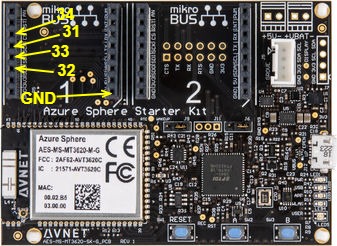
Next we will wire these GPIO pins 31,32,33,34 on the Azure Sphere. We will also connect the ground of our power source to the ground pin. Just like with the Arduino, I would not try to drive motors directly from the power provided from the Azure Sphere. With this small motor it might not be too bad, but it could definitely cause issues with motors that could draw more current.
IN1 = GPIO 32
IN2 = GPIO 33
IN3 = GPIO 31
IN4 = GPIO 34
Take note that the Azure Sphere's pins aren't in exactly sequential order.
Finally we will connect the driver to the power source by plugging the '+' pin
to the positive of our power source and the ground pin '-' to the ground of our power source
My final setup was pretty much this
Grab the code from my Github here Github
the solution is in the "StepperMotorTutorial" folder.
A lot of the basic setup code comes from the Azure Sphere samples repo here. I am not a C developer(or an engineer) by trade and am still getting use to the differences of the language vs languages that I use prominently professionally day to day. The code will be "rough" and very basic, but should be very easy to follow. The code also uses the green LED and "A" user button. the button is used as the switch that starts the motor stepping process. The LED will light up to let us know when the motor should be turning.
Sections to take note of:
app_manifest.json
{
 "SchemaVersion": 1,
 "Name": "AzureMotorTest",
 "ComponentId": "9f089a19-d540-4b61-b413-693080f67687",
 "EntryPoint": "/bin/app",
 "CmdArgs": [],
 "Capabilities": {
   "AllowedConnections": [],
   "Gpio": [ 9, 12, 31, 32, 33, 34 ],
   "Uart": [],
   "WifiConfig": false
 },
 "ApplicationType": "Default"
}
This file notifies the system of the pins we intend to use. We must put in our GPIO pins for the inputs to the motor. If you use different pins remember to make you change here and to the code accordingly. We use the pins 31-34 for the motor inputs. PIN 9 for the on board green LED and PIN 12 for the 'A' user button.
The other section of import is the stepper motor's loop. This is the meat of what we are doing. This is timed to fire off in the smallest subset of time that the motor should move it's next step when using full steps. The code is looking for a bool that should be set when the button is pressed and then determines what is the next step it should go to.
static void StepperMotorEventHandler(EventData *eventData)
{
if (ConsumeTimerFdEvent(stepperMotorTimerFd) != 0)
{
terminationRequired = true;
return;
}
if (isMotorTurning)
{
switch (stepNumber)
{
case 0:
Log_Debug("STEP 0\n");
GPIO_SetValue(IN1, GPIO_Value_Low);
GPIO_SetValue(IN2, GPIO_Value_High);
GPIO_SetValue(IN3, GPIO_Value_High);
GPIO_SetValue(IN4, GPIO_Value_High);
break;
case 1:
Log_Debug("STEP 1\n");
GPIO_SetValue(IN1, GPIO_Value_High);
GPIO_SetValue(IN2, GPIO_Value_Low);
GPIO_SetValue(IN3, GPIO_Value_High);
GPIO_SetValue(IN4, GPIO_Value_High);
break;
case 2:
Log_Debug("STEP 2\n");
GPIO_SetValue(IN1, GPIO_Value_High);
GPIO_SetValue(IN2, GPIO_Value_High);
GPIO_SetValue(IN3, GPIO_Value_Low);
GPIO_SetValue(IN4, GPIO_Value_High);
break;
case 3:
Log_Debug("STEP 3\n");
GPIO_SetValue(IN1, GPIO_Value_High);
GPIO_SetValue(IN2, GPIO_Value_High);
GPIO_SetValue(IN3, GPIO_Value_High);
GPIO_SetValue(IN4, GPIO_Value_Low);
break;
default:
break;
}
stepNumber++;
if (stepNumber == 4)
stepNumber = 0;
}
else
{
GPIO_SetValue(IN1, GPIO_Value_High);
GPIO_SetValue(IN2, GPIO_Value_High);
GPIO_SetValue(IN3, GPIO_Value_High);
GPIO_SetValue(IN4, GPIO_Value_High);
}
}
You should be all set. The problems that you may run into are wiring. Just make sure that driver's wires are set to the correct pins.
I'd love to hear you feedback.


Comments