


This project was the first RTL design I implemented on an FPGA to interface it with an external component. I had previously experimented with the Altera MAX II EPM240 CPLD to implement simple digital logic such as multiplexers, decoders, counters for blinking LEDs, and even UART transmitters. Although I had a lot of fun programming this CPLD, it didn't take long for me to realize that I wasn't going to accomplish much with just 240 logic elements. I invested in an FPGA board and ended up choosing the Altera Cyclone IV EP4CE6E22C8N board on AliExpress for its relatively lower cost and assortment of onboard peripherals.
Being the first project with my new board, I decided to do something "Hello Worldy" that didn't involve blinking an LED, since I had already tried that with my CPLD. I eventually went with the 4-digit 7-segment display on the board and tasked myself to create a counter that counts from 0 to 9999, incrementing every second and wrapping around to 0 from the maximum value of 9999. My HDL of choice was VHDL as it was the language I was familiar with at the time.
HardwareThe 4-digit 7-segment display on the EP4CE6E22C8N board has a common anode configuration. Since the anodes are tied to a common terminal, a high voltage is required to activate each digit of the device so that the LEDs in the segments can be independently controlled (turned on using a low voltage). All four digits share the same pins for controlling individual segments (they are multiplexed). As a result of the multiplexed pins, data with distinct digits can only be displayed by selecting one digit of the 7-segment display at a time, effectively displaying the value for each digit and quickly switching to the next such that the human eye won't be able to perceive the transition.
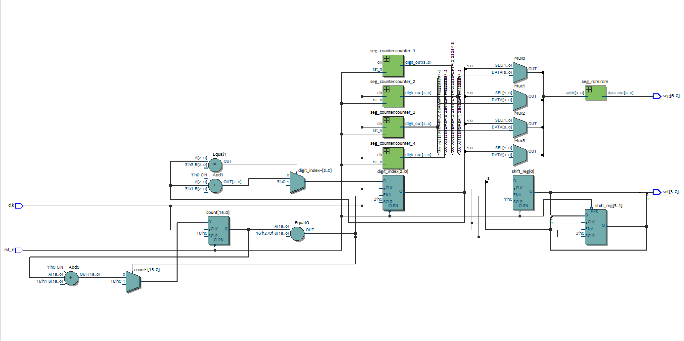
The design consists of three VHDL files/modules, namely: seg_display.vhd, seg_counter.vhd, and seg_rom.vhd. The logic/bit combinations for displaying numbers 0 to 9 are stored in the ROM module. The counter module increments from 0 to 9 at a rate determined by the place value of the digit on the 7-segment display. There are 4 digits: ones, tens, hundreds, and thousands. Counters are instantiated to update the value of the digits such that the counter for the next digit (to the left) is 10 times slower than the previous. Although this design works, it is very inefficient because it requires four active counters. A better solution is to convert the values to be displayed from binary to BCD using the Double Dabble algorithm (I learnt this several months later). The segment display VHDL module instantiates the counters and ROM module and also switches between the digits of the 7-segment display in order to give a proper display of distinct digits as explained in the Hardware section of this post.
Building the projectI made a few adjustments to the project over the years by making it somewhat platform-independent. You can successfully build it on Windows and Ubuntu without issues using Tcl scripts. Kindly check the link to my GitHub repository for additional documentation with instructions on how to do this if you're interested.
Video demoAttached to this Hackster post is a link to a video demonstrating the project in action: Demo
What can be improvedI created this project back in 2024 when I was still new to RTL design and HDLs. Some of the major improvements that can be made include:
- Replacing the four counters with a simple logic that converts from binary to BCD, and using the BCD values to drive the display.
- Writing one generic/customizable counter module that can be instantiated in different parts of the design with appropriate parameters.
- The design uses an asynchronous reset. It'll be better to use an asynchronous reset that de-asserts synchronously in order to prevent metastability issues.
- A top-level file with only wired-up instantiations of other design modules. This version uses the seg_display.vhd as the top design but also includes a lot of logic.
Thanks for reading.


Comments