
Hardware components | ||||||
 |
| × | 1 | |||
| × | 1 | ||||
| × | 1 | ||||
Software apps and online services | ||||||
| ||||||
A thermographic camera (also called an infrared camera or thermal imaging camera) is a device that forms an image using infrared radiation, similar to a common camera that forms an image using visible light ( definition from en.wikipedia.org ). How view looks from thermographic camera you can see on figure 1.
In this project I will show how to make one pixel from thermographic camera. I will use Texas Instruments IR temperature sensor TMP006 and Tiva C Series Launchpad.
TMP006
The TMP006 is a non-contact infrared (IR) temperature sensor with a digital interface. The sensor can measure object and ambient temperature. Infrared sensor voltage range is specified from –40°C to +125°C. Low power consumption along with low operating voltage makes the device suitable for battery-powered applications. The low package enables standard high volume assembly methods.
- Complete Solution 1,6×1,6 mm Wafer Chip-Scale Package (WCSP) Device (DSBGA)
- Sensor Voltage: 7 μV/°C, Local Temperature: –40°C to +125°C
- SMBus™-Compatible Interface
- Low Supply Current: 240 μA, Low Minimum Supply Voltage: 2.2 V
When measuring the temperature of an object using the TMP006, there are several fundamental measurement constraints that must be followed to ensure the accuracy of the object temperature calculation. The two primary constraints are:
1. The surface emissivity of the target object
2. The placement of the TMP006, relative to the size of the target, angle and distance between TMP006 and target
1. The emissivity of an object is defined as the ability of an object surface to radiate energy relative to an ideal emitter. An ideal emitter, also called a black body, has an emissivity value of 1. When using the TMP006 for target object surface temperature calculations, it is essential that the surface of the target object be able to emit sufficient IR radiation to be accurately detected by the IR sensor in the TMP006.
Targets with very low emissivity values emit less IR radiation, and therefore produce smaller signals, which are harder for the TMP006 to capture and measure. Polished and shiny metal objects have surface emissivity values that are typically too low for use with the TMP006. To measure the surface temperature of an object with a very low emissivity, it can be painted with lampblack paint which has an emissivity of 0.96. As a design guideline, the TMP006 should only be used to calculate the surface temperature of target objects with emissivity values greater than 0.7, and preferably greater than 0.9. The emissivity values of common objects are listed on figure 3.
2. The ability of the TMP006 to accurately calculate the temperature of a target depends on ability of the IR sensor to capture the majority of its signal from the target. This capture effectiveness, in turn, depends on two factors: the angle of incidence and the distance of the TMP006 from the target.
Dependence of the TMP006 on the angle of incidence compared to the IR signal absorption is shown on figure 4. This figure shows that the majority of the received signal comes from IR sources located at 0° angles of incidence.
As a design guideline, user should place the TMP006 directly underneath the target object with the surface of the target parallel to the TMP006, so the angle of incidence between them is 0°.
The distance that the TMP006 should be placed from the target is largely dictated by the size of the target. Smaller targets must be placed closer to the TMP006 to ensure that the majority of the IR signal captured by the sensor is emitted from the target. To ensure at least 90% of the IR signal that the sensor captures is from the target a circular target should be placed at a distance less than one-half of the radius of the target.
How the percentage of the final IR signal captured by the TMP006 depends on the radius of the target and its distance from the TMP006 is shown on figure 5.
Recomended distance ( for yields > 90% signal ) is equal: d < 1/2 r
where: d- distance between TM006 and target, r - radius of the target
informations about TMP006 from Texas Instruments materials
Hardware
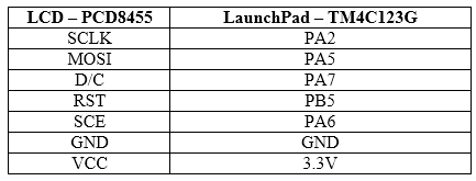
In this project I used Tiva C Series LaunchPad, Sensor Hub BoosterPack (with TMP006) and monochromatic NOKIA 5110/3310 graphic LCD (for example this boosterpack) with resolution 84x48 and PCD8455 driver. LaunchPad and BoosterPack were connected together ( figure 6 )
Tiva C Series LaunchPad and LCD EVM connection are shown in Hardware section. In project I used wire connection. Five signal ( SCLK/MOSI/D-C/RST/SCE ) lines and two power lines ( GND/VCC ) were used.
Software
Source code is compatible with Tiva C Series TM4C123G microcontroller . Application was written in C language. IAR Embedded Workbench for ARM IDE was used.
In application TMP006 communication procedures were implemented. Project code is available in software section. Main.c file source code is shown on listing 1.
In main section firstly general settings of TM4C123G microcontroller are configured ( system clock, gpio and uart communication ). After that I2C interface and TMP006 sensor are configured. Sensor TMP006 is set in cyclic measurements mode ( one measurement for second ) and line #DRDY is used ( low state when measurement is ready for read ). Next low power mode for TM4C123G microcontroller and interrupts usage are activated. Finally LCD is configured.
In the main loop of the program microcontroller TM4C123G waiting in sleep mode for signal from #DRDY line. When falling edge on #DRDY occurs ( measurements data are ready) . Microcontroller TM4C123G is waking up and reading measurements data from TMP006 sensor ( ambient and object temperature in degrees Celcius ). Then, the result of measurement are sent using the UART interface and are displayed on the LCD. Microcontroller TM4C123G is sleeping. After one second work cycle is repeat.
Work
During the test I measure the temperature of the mug of tea. Device during work is shown on figure 7.
Data from uart are shown below.
Difference between object temperature ( mug of tea) and ambient temperature is about 20 °C. How Thermographic Camera Pixel should look ? I propose scale and value like shown on figure 8.
For better and more clear functionality RGB diode could be used ( RGB diode like thermographic camera pixel ). Colour of diode/pixel should be changed by device.
Lukasz Krysiewicz, Poland


Comments