
![LogicTronix [FPGA Design + Machine Learning Company]](https://hackster.imgix.net/uploads/attachments/1123066/_SyVIfEqFUU.blob?auto=compress%2Cformat&w=40&h=40&fit=min&dpr=2)
Software apps and online services | ||||||
| ||||||
| ||||||
 |
| |||||
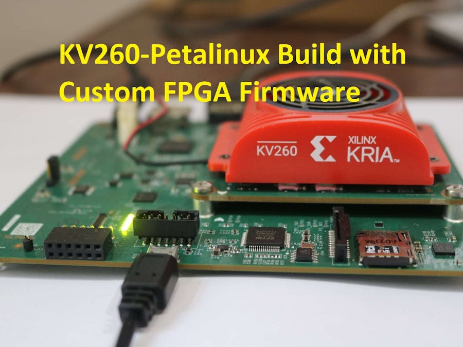
This tutorial is on "how to create petalinux build KV260, a Kria based FPGA board with Custom FPGA firmware. This tutorial is based on Petalinux 2020.2 [link] with installed Kria K26 Special Release for petalinux 2020.2. We also have used Kria KV260 Starter Kit 2020.2.2 BSP in this tutorial.
After you installed Petalinux 2020.2 and then Kria K26 Special Release for petalinux 2020.2 on your Linux system you are then ready to start on Petalinux development for KV260-Kria board.
We have listed all the steps for creating petalinux build with custom FPGA firmware in following section:
1. Create the project from BSP- Run the following command to create a new Petalinux project from downloaded BSP for KV260 starter kit.
$ petalinux-create -t project -s xilinx-k26-starterkit-2020.2.2-final.bsp -n kv260_custom
$ cd kv260_custom- Default Petalinux project from BSP is configured for K26 SOM and to include KV260 starter kit specific packages,
BOARD_VARIANTvariable need to be set in config. For this, set the variable using following command:
$ echo 'BOARD_VARIANT = "kv"' >> project-spec/meta-user/conf/petalinuxbsp.confNow, add the application packagegroup into the rootfs config such that it is listed in menuconfig and necessary library required for custom application is installed.
$ echo 'CONFIG_packagegroup-kv260-smartcam' >> project-spec/meta-user/conf/user-rootfsconfigfpgamanager_custom bitbake class is a helper class to generate a set of FPGA firmware binaries. The following hardware design hand-off artifacts are required:
- PL Bitstream file generated from Vivado design
- Xclbin file exported from Vitis design
- Device tree overlay file, which need to be generated from hardware design xsa file.
For the third step, device tree overly file is generated from hardware design xsa file through xsct available with Vitis Design tool and also with Petalinux installation.
First download the repository for device-tree-xlnxFor starting xsct terminal, find the xsct binaries at <Petalinux_2020_2_2 installation folder>/tools/xsct and run the xsct terminal
$ cd <Petalinux_2020_2_2 installation folder>/tools/xsct
$ xsct
This will start the XSCT.Open XSA/HDF file
hsi open_hw_design <design_name>.<xsa|hdf>Set repository path (clone done in previous step in SDK) (
hsi set_repo_path <path to device-tree-xlnx repository>Create SW design and setup CPU.
hsi create_sw_design device-tree -os device_tree -proc psu_cortexa53_0Setting for creating device overlay file
hsi set_property CONFIG.dt_overlay true [hsi::get_os]Generate DTS/DTSI files to folder my_dts where output DTS/DTSI files will be generated
hsi generate_target -dir my_dtsClean up.
hsi close_hw_design [hsi::current_hw_design]
exit
This will generate the device tree files at my_dts folder. Depending upon hadware desing corresponding PL.dtsi file is fount in my_dts folder.
Now open the pl.dtsi file for adding the node for DPU hardware at the end of the file.
/ zocl /
	fragment@3 {
		target = <&amba>;
		overlay11: _overlay_ {
			zocl: zyxclmm_drm {
				compatible = "xlnx,zocl";
				status = "okay";
				interrupt-parent = <&gic>;
				interrupts = <0 89  4>, <0 90  4>, <0 91  4>, <0 92  4>,
					     <0 93  4>, <0 94  4>, <0 95  4>, <0 96  4>;
			};
		};
	};
Now copy the device tree overlay file into the project folder and run following commands to create the firmware recipe
$ petalinux-create -t apps --template fpgamanager -n user-firmware --enable --srcuri "user.bit user.dtsi user.xclbin"- Add the necessary packages depending upon the application requirement. To set the required packages run following command:
$ petalinux-config -c rootfsEnabling MatchBox
This will open the menuconfig, from which one can select various packages.
Petalinux Package Groups -> packagegroup-petalinux-matchbox -> packagegroup-petalinux-matchboxEnable X11
Petalinux Package Groups -> packagegroup-petalinux-x11 -> packagegroup-petalinux-x11After configuring the rootfs, next build the image using following commands:
$ petalinux-build
$ petalinux-package --wic --bootfiles "ramdisk.cpio.gz.u-boot boot.scr Image system.dtb"
The generated image file will be located at images/linux/petalinux-sdimage.wic.
Now this WIC image is 4GB by size. To share through google drives or any sharing services, image size can be decreased by using any compression application like zip
Now flash the image into SD card using Balena Etcher.
5. Booting KV260After flashing SD card, please insert SD card into KV260, as shown below. Now connect the power adapter, HDMI or DP port connection and USD-UART for JTAG/UART communication with FPGA Board. This build does not require USB camera or MIPI camera so, no need to connect those here.
Now you can power-up the KV260. Connect the UART connection at serial port with 115200 baud rate, if you have connected HDMI or DP port monitor then you will also see the matchbox based desktop in the Monitor.
5. BOOT log from KV260 in Serial Terminal or Monitor [HDMI/DP-port]The Boot log on UART terminal or at Monitor looks like this:
The connection setup overall can be viewed as below. This is the pictorial setup of after we enabled the matchbox.
Meantime, if you get confusion over this development steps then you can contact for support at info@logictronix.com.
LogicTronix is "Design Service Partner of Xilinx Kria SoM for AI/ML", we have expertise on "accelerating ML applications and developing ML solutions based on Kria SoM or K26 SoM Family or KV260 Board, for more information please visit: https://www.xilinx.com/products/som/kria.html#ai2
![LogicTronix [FPGA Design + Machine Learning Company]](https://hackster.imgix.net/uploads/attachments/1123066/_SyVIfEqFUU.blob?auto=compress%2Cformat&w=60&h=60&fit=min&dpr=2)


Comments