

Hardware components | ||||||
 |
| × | 1 | |||
| × | 1 | ||||
Software apps and online services | ||||||
| ||||||
| ||||||
Hand tools and fabrication machines | ||||||
 |
| |||||
| ||||||
| ||||||
The Xilinx XC5200 series represents a significant chapter in the history of programmable logic. As these chips become increasingly rare, I wanted to document a practical implementation using the XC5202-6PQ100I. The goal was to bridge the gap between vintage hardware and modern design workflows, proving that these "classic" chips still have life in them for digital logic experimentation.
The SolutionThis project serves as a foundational guide for setting up and configuring the XC5202-6PQ100I. By focusing on a simple yet effective digital logic design, I have established a baseline that allows for more complex future implementations on this 3K-gate device.
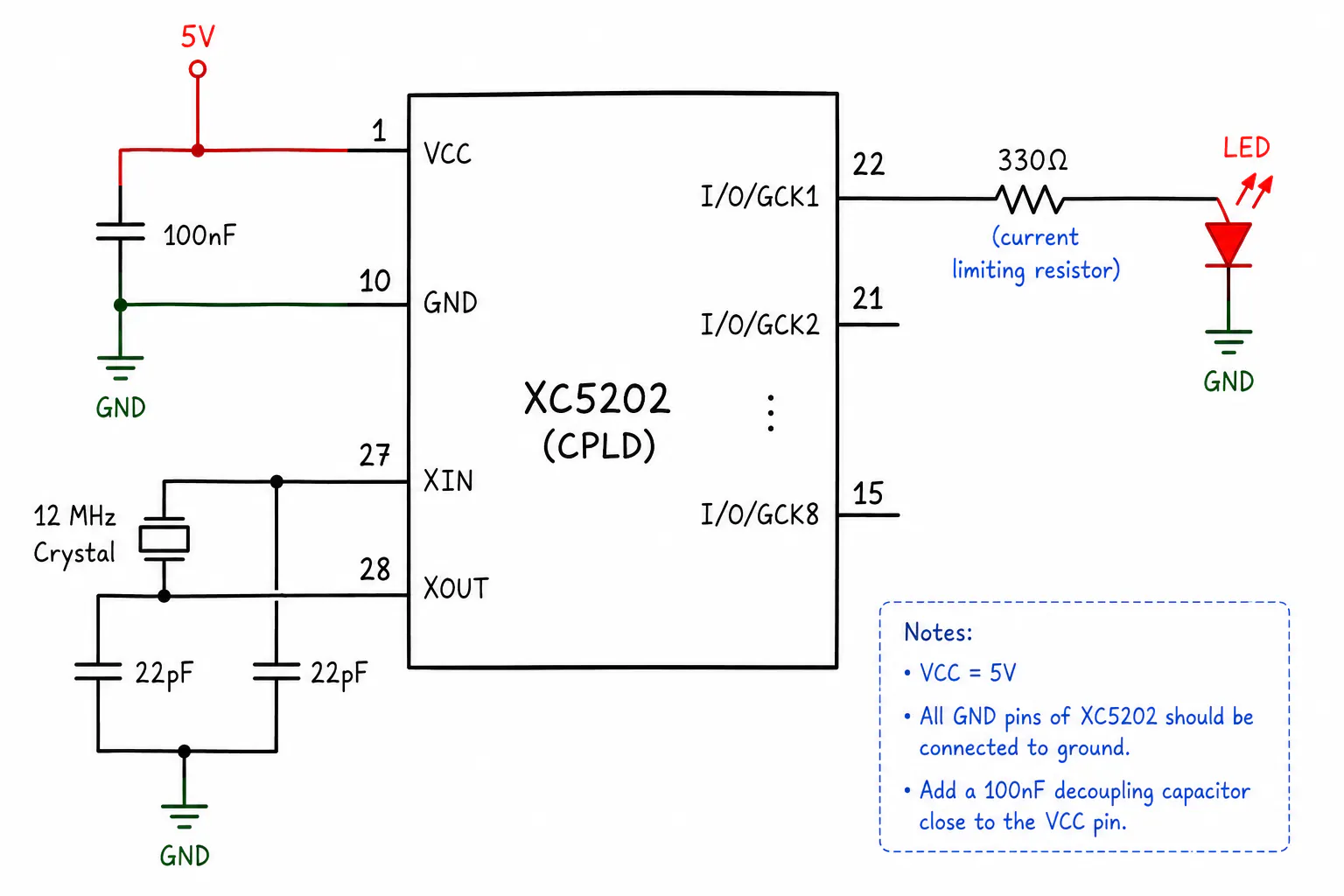
How it Works1. Hardware ArchitectureThe XC5202-6PQ100I features a 100-pin PQFP package. Key specs include:
Logic Gates: 3, 000 equivalent gates
- Logic Gates: 3, 000 equivalent gates
CLBs: 64 Configurable Logic Blocks
- CLBs: 64 Configurable Logic Blocks
Voltage: 5V operation (a key consideration for interfacing with modern components)
- Voltage: 5V operation (a key consideration for interfacing with modern components)
Using Xilinx ISE WebPACK, I developed the bitstream for the chip. The process involves:
Defining logic gates and I/O constraints.
- Defining logic gates and I/O constraints.
Generating the configuration file.
- Generating the configuration file.
Utilizing a JTAG-compatible programmer to load the design onto the FPGA.
- Utilizing a JTAG-compatible programmer to load the design onto the FPGA.
(Note: Upload your files to the Attachments tab first, then link them here)
You can download the full project schematics and the Verilog/VHDL source code from the Attachments section.
- You can download the full project schematics and the Verilog/VHDL source code from the Attachments section.
Working with the XC5202-6PQ100I has been a great way to understand the evolution of FPGA architecture. It is a reminder that you don’t always need the latest multi-million gate SoC to learn the fundamentals of digital design.
Tips for your Story:Add Images: Use the image icon in the editor to upload clear photos of your board, the wiring, or your setup.
- Add Images: Use the image icon in the editor to upload clear photos of your board, the wiring, or your setup.
Highlight Code: If you have code, click the </> icon to paste it into a code block. It makes it look much more professional.
- Highlight Code: If you have code, click the
</>icon to paste it into a code block. It makes it look much more professional.
Bold Keywords: Use the B button to bold key terms like XC5202-6PQ100I, FPGA, and 5V, so people skimming your project catch the important info.
- Bold Keywords: Use the
Bbutton to bold key terms like XC5202-6PQ100I, FPGA, and 5V, so people skimming your project catch the important info.


Comments