

Hardware components | ||||||
 |
| × | 1 | |||
 |
| × | 1 | |||
| × | 1 | ||||
Software apps and online services | ||||||
| ||||||
In the last tutorial, we created an I2S transmitter to output some audio data from an internal ROM. In the next step, we add an AXI-Stream Interface to this I2S transmitter, so we can connect the transmitter with the Processing System of the ZYNQ to output some audio data from an SD card.
For this purpose, a new top design called AXIS_I2S is created. This design should have the following interface:
This block design results in the following entity:
entity AXIS_I2S is
    Generic (   RATIO   : INTEGER := 8;
                WIDTH   : INTEGER := 16
                );
    Port (  MCLK        : in STD_LOGIC;
            nReset      : in STD_LOGIC;
            LRCLK       : out STD_LOGIC;
            SCLK        : out STD_LOGIC;
            SD          : out STD_LOGIC;
            ACLK        : in STD_LOGIC;
            ARESETn     : in STD_LOGIC;
            TDATA_RXD   : in STD_LOGIC_VECTOR(31 downto 0);
            TREADY_RXD  : out STD_LOGIC;
            TVALID_RXD  : in STD_LOGIC
            );
end AXIS_I2S;
The ratio of SCLK to MCKL is defined via the parameter RATIO and the width of a data word per channel via the parameter WIDTH.
This implementation only supports 16-bit data words per channel (i.e. 32 bit for stereo). The following code must be adapted for larger bus widths.
The following components must be implemented in the design:
- A clock prescaler to create the input clock for the I2S transmitter
- An AXI-Stream slave interface
- The control logic for the I2S transmitter
A process is created for the divider, which counts up a counter on the rising clock edge of MCLK and switches the signal SCLK_Int after half the period.
process
    variable Counter    : INTEGER := 0;
begin
    wait until rising_edge(MCLK);
    if(Counter < ((RATIO / 2) - 1)) then
        Counter := Counter + 1;
    else
        Counter := 0;
        SCLK_Int <= not SCLK_Int;
    end if;

    if(nReset = '0') then
        Counter := 0;
        SCLK_Int <= '0';
    end if;
end process;
The next step is to implement the AXI-Stream interface. A state machine is used for this:
process
begin
    wait until rising_edge(ACLK);
    case CurrentState is
        when State_Reset =>
            Tx_AXI <= (others => '0');
            CurrentState <= State_WaitForTransmitterReady;

        when State_WaitForTransmitterReady =>
            if(Ready_AXI = '1') then
                TREADY_RXD <= '1';
                CurrentState <= State_WaitForValid;
            else
                TREADY_RXD <= '0';
                CurrentState <= State_WaitForTransmitterReady;
            end if;
        when State_WaitForValid =>
            if(TVALID_RXD = '1') then
                TREADY_RXD <= '0';
                Tx_AXI <= TDATA_RXD;
                CurrentState <= State_WaitForTransmitterBusy;
            else
                TREADY_RXD <= '1';
                CurrentState <= State_WaitForValid;
            end if;
        when State_WaitForTransmitterBusy =>
            if(Ready_AXI = '0') then
                CurrentState <= State_WaitForTransmitterReady;
            else
                CurrentState <= State_WaitForTransmitterBusy;
            end if;
    end case;
    if(ARESETn = '0') then
            CurrentState <= State_Reset;
    end if;
end process;
After a reset, the machine changes from the State_Reset state to the State_WaitForTransmitterReady state, where it waits for the ready signal from the I2S transmitter. As soon as the transmitter is ready, the TREADY_RXD signal of the AXI-Stream interface is set, whereby the master is informed that the slave is ready to receive data. The slave then changes to the State_WaitForValid state.
In this state, the slave waits for the master to set the TVALID_RXD signal to mark valid data. As soon as the signal is set, the data is written to an internal FIFO. The machine then changes to the State_WaitForTransmitterBusy state.
Now the state machine waits for the I2S transmitter to start transmitting the data and to delete the ready signal. As soon as this is done, the machine switches back to the State_WaitForTransmitterReady state and waits again until the I2S transmitter is ready.
With that, the AXI-Stream Interface would be finished in theory. Unfortunately, it gets a bit tricky at the end, since the current circuit design uses two different clock domains:
- The clock domain for ACLK
- The clock domain for MCLK
In general, these two clock signals cannot be generated from a clock source (e.g. via a clock divider), since the AXI interface typically runs at 100 MHz and the audio interface requires clock rates that can be neatly divided down to the sampling frequency, such as e.g. 12.288 MHz. As a result, timing errors occur during implementation due to excessive worst negative slack (WNS) and total negative slack (TNS):
Also, the risk of incorrect data due to the metastability of the flip-flops occurring with different clock domains is very high. Metastability occurs a. then when a flip-flop switches and the data changes at that very moment.
Therefore, the signals that are used by the individual clock domains must be transferred to the other clock domain in each case via corresponding circuits. Xilinx describes corresponding macros in document UG953 that can be used for this purpose.
- xpm_cdc_gray - This function block uses Gray code to transfer a data bus from one clock domain (src) to another clock domain (dest).
- xpm_cdc_single - Converts a single signal from one clock domain (src) to another clock domain (dest).
The examples of the macros can be used directly for the VHDL code:
xpm_cdc_Data : xpm_cdc_handshake generic map ( DEST_EXT_HSK => 0,
                                               DEST_SYNC_FF => 4,
                                               INIT_SYNC_FF => 0,
                                               SIM_ASSERT_CHK => 0,
                                               SRC_SYNC_FF => 4,
                                               WIDTH => (2 * WIDTH)
                                               )
                              port map (  src_clk => ACLK,
                                          src_in => Data_Fast,
                                          dest_clk => MCLK,
                                          dest_out => Data_Slow,
                                          dest_ack => '0',
                                          src_send => src_send,
                                          src_rcv => src_rcv,
                                          dest_req => dest_req
                                          );

xpm_cdc_Ready : xpm_cdc_single generic map ( DEST_SYNC_FF => 4,
                                             SRC_INPUT_REG => 1
                                             )
                                 port map (  src_clk => MCLK,
                                             src_in => Ready_Transmitter,
                                             dest_clk => ACLK,
                                             dest_out => Ready_AXI
                                             );
Finally, the I2S transmitter must be inserted and the generated signals passed on.
Transmitter : I2S_Transmitter generic map ( WIDTH => WIDTH
                                            )
                                  port map( Clock => SCLK_Int,
                                            nReset => nReset,
                                            Ready => Ready_Transmitter,
                                            Tx => Tx_Transmitter,
                                            LRCLK => LRCLK,
                                            SCLK => SCLK,
                                            SD => SD
                                            );
The AXI-Stream Interface for the I2S transmitter is now ready and ready for use. The complete code should now look like this:
library IEEE;
use IEEE.STD_LOGIC_1164.ALL;
library xpm;
use xpm.vcomponents.all;

entity AXIS_I2S is
    Generic (   RATIO   : INTEGER := 8;
                WIDTH   : INTEGER := 16
                );
    Port (  MCLK        : in STD_LOGIC;
            nReset      : in STD_LOGIC;
            LRCLK       : out STD_LOGIC;
            SCLK        : out STD_LOGIC;
            SD          : out STD_LOGIC;
            ACLK        : in STD_LOGIC;
            ARESETn     : in STD_LOGIC;
            TDATA_RXD   : in STD_LOGIC_VECTOR(31 downto 0);
            TREADY_RXD  : out STD_LOGIC;
            TVALID_RXD  : in STD_LOGIC
            );
end AXIS_I2S;

architecture AXIS_I2S_Arch of AXIS_I2S is
    type AXIS_State_t is (State_Reset, State_WaitForTransmitterReady, State_WaitForValid, State_WaitForTransmitterBusy);
    signal CurrentState : AXIS_State_t    := State_Reset;
    signal Tx_AXI : STD_LOGIC_VECTOR(((2 * WIDTH) - 1) downto 0) := (others => '0');
    signal Ready_AXI : STD_LOGIC;
    signal Tx_Transmitter : STD_LOGIC_VECTOR(((2 * WIDTH) - 1) downto 0) := (others => '0');
    signal Ready_Transmitter    : STD_LOGIC;
    signal SCLK_Int             : STD_LOGIC := '0';
    component I2S_Transmitter is
        Generic (   WIDTH   : INTEGER := 16
                    );
        Port (  Clock   : in STD_LOGIC;
                nReset  : in STD_LOGIC;
                Ready   : out STD_LOGIC;
                Tx      : in STD_LOGIC_VECTOR(((2 * WIDTH) - 1) downto 0);
                LRCLK   : out STD_LOGIC;
                SCLK    : out STD_LOGIC;
                SD      : out STD_LOGIC
                );
    end component;

begin

    Transmitter : I2S_Transmitter generic map ( WIDTH => WIDTH
                                                )
                                  port map(     Clock => SCLK_Int,
                                                nReset => nReset,
                                                Ready => Ready_Transmitter,
                                                Tx => Tx_Transmitter,
                                                LRCLK => LRCLK,
                                                SCLK => SCLK,
                                                SD => SD
                                                );
   xpm_cdc_Data : xpm_cdc_gray generic map (    DEST_SYNC_FF => 4,
                                                SIM_ASSERT_CHK => 0,
                                                SIM_LOSSLESS_GRAY_CHK => 0,
                                                WIDTH => (2 * WIDTH)
                                                )
                                    port map (  src_clk => ACLK,
                                                src_in_bin => Tx_AXI,
                                                dest_clk => MCLK,
                                                dest_out_bin => Tx_Transmitter
                                                );
   xpm_cdc_Ready : xpm_cdc_single generic map ( DEST_SYNC_FF => 4,
                                                SRC_INPUT_REG => 1
                                                )
                                    port map (  src_clk => MCLK,
                                                src_in => Ready_Transmitter,
                                                dest_clk => ACLK,
                                                dest_out => Ready_AXI
                                                );
    process
        variable Counter    : INTEGER := 0;
    begin
        wait until rising_edge(MCLK);
        if(Counter < ((RATIO / 2) - 1)) then
            Counter := Counter + 1;
        else
            Counter := 0;
            SCLK_Int <= not SCLK_Int;
        end if;

        if(nReset = '0') then
            Counter := 0;
            SCLK_Int <= '0';
        end if;
    end process;

    process
    begin
        wait until rising_edge(ACLK);
        case CurrentState is
            when State_Reset =>
                Tx_AXI <= (others => '0');
                CurrentState <= State_WaitForTransmitterReady;
            when State_WaitForTransmitterReady =>
                if(Ready_AXI = '1') then
                    TREADY_RXD <= '1';
                    CurrentState <= State_WaitForValid;
                else
                    TREADY_RXD <= '0';
                    CurrentState <= State_WaitForTransmitterReady;
                end if;
            when State_WaitForValid =>
                if(TVALID_RXD = '1') then
                    TREADY_RXD <= '0';
                    Tx_AXI <= TDATA_RXD;
                    CurrentState <= State_WaitForTransmitterBusy;
                else
                    TREADY_RXD <= '1';
                    CurrentState <= State_WaitForValid;
                end if;
            when State_WaitForTransmitterBusy =>
                if(Ready_AXI = '0') then
                    CurrentState <= State_WaitForTransmitterReady;
                else
                    CurrentState <= State_WaitForTransmitterBusy;
                end if;
        end case;
        if(ARESETn = '0') then
            CurrentState <= State_Reset;
        end if;
    end process;
end AXIS_I2S_Arch;
Next, we want to use this interface to read wave files from an SD card using the processing system and output the music using a CS4344 D/A converter via a connected speaker.
The following IP cores are required for the project:
- The I2S transmitter with the AXI-Stream Interface
- A Processing System to read the data from the SD card and write them into a FIFO
- An AXI-Stream FIFO
- A Clocking Wizard to generate the audio clock
The Clocking Wizard generates the clock, which is then used as the master clock for the CS4344. The output clock can be adapted to the sampling rate of the audio file via the AXI-Lite interface. The Clocking Wizard is initialized with a 12.288 MHz clock for 48 kHz audio signals.
The AXI-Stream FIFO serves as a link between the processing system and the I2S transmitter. The processing system writes data to the FIFO via the AXI-Lite (or AXI) interface and this then streams the data to the I2S transmitter.
A bitstream is created from the design and after that, the software can be developed.
The xilffs FAT library from Xilinx is required to read the SD card, which must be integrated into the Board Support Package of the Vitis project (don´t forget to enable the LFN option to support large file names):
In the first step, the software uses the AudioPlayer_Init function to initialize the audio player and thus the FIFO, the GIC, and the interrupt handler, as well as the clocking wizard and the SD card.
u32 AudioPlayer_Init(void)
{
	xil_printf("[INFO] Looking for FIFO configuration...\r\n");
	_Fifo_ConfigPtr = XLlFfio_LookupConfig(XPAR_FIFO_DEVICE_ID);
	if(_Fifo_ConfigPtr == NULL)
	{
		xil_printf("[ERROR] Invalid FIFO configuration!\r\n");
		return XST_FAILURE;
	}

	xil_printf("[INFO] Initialize FIFO...\r\n");
	if(XLlFifo_CfgInitialize(&_Fifo, _Fifo_ConfigPtr, _Fifo_ConfigPtr->BaseAddress) != XST_SUCCESS)
	{
		xil_printf("[ERROR] FIFO initialization failed!\n\r");
		return XST_FAILURE;
	}

	xil_printf("[INFO] Looking for GIC configuration...\r\n");
	_GIC_ConfigPtr = XScuGic_LookupConfig(XPAR_PS7_SCUGIC_0_DEVICE_ID);
	if(_GIC_ConfigPtr == NULL)
	{
		xil_printf("[ERROR] Invalid GIC configuration!\n\r");
		return XST_FAILURE;
	}

	xil_printf("[INFO] Initialize GIC...\r\n");
	if(XScuGic_CfgInitialize(&_GIC, _GIC_ConfigPtr, _GIC_ConfigPtr->CpuBaseAddress) != XST_SUCCESS)
	{
		xil_printf("[ERROR] GIC initialization failed!\n\r");
		return XST_FAILURE;
	}

	xil_printf("[INFO] Setup interrupt handler...\r\n");
	XScuGic_SetPriorityTriggerType(&_GIC, XPAR_FABRIC_FIFO_INTERRUPT_INTR, 0xA0, 0x03);
	if(XScuGic_Connect(&_GIC, XPAR_FABRIC_FIFO_INTERRUPT_INTR, (Xil_ExceptionHandler)AudioPlayer_FifoHandler, &_Fifo) != XST_SUCCESS)
	{
		xil_printf("[ERROR] Can not connect interrupt handler!\n\r");
		return XST_FAILURE;
	}
	XScuGic_Enable(&_GIC, XPAR_FABRIC_FIFO_INTERRUPT_INTR);

	xil_printf("[INFO] Enable exceptions...\r\n");
	Xil_ExceptionInit();
	Xil_ExceptionRegisterHandler(XIL_EXCEPTION_ID_INT, (Xil_ExceptionHandler)XScuGic_InterruptHandler, &_GIC);
	Xil_ExceptionEnable();

	xil_printf("[INFO] Enable FIFO interrupts...\r\n");
	XLlFifo_IntClear(&_Fifo, XLLF_INT_ALL_MASK);

	xil_printf("[INFO] Initialize Clocking Wizard...\r\n");
	if((ClockingWizard_Init(&_ClkWiz, XPAR_CLOCKINGWIZARD_BASEADDR) || ClockingWizard_GetOutput(&_ClkWiz, &_AudioClock))!= XST_SUCCESS)
	{
		xil_printf("[ERROR] Clocking Wizard initialization failed!\n\r");
		return XST_FAILURE;
	}
	xil_printf("[INFO] Mount SD card...\r\n");
	if(SD_Init())
	{
		xil_printf("[ERROR] Can not initialize SD card!\n\r");
		return XST_FAILURE;
	}

	return XST_SUCCESS;
}
As soon as the initialization is completed, the function AudioPlayer_LoadFile is called to load the file Audio.wav from the SD card.
if(AudioPlayer_LoadFile("Audio.wav"))
{
	xil_printf("[ERROR] Can not open Audio file!\n\r");
	return XST_FAILURE;
}

u32 AudioPlayer_LoadFile(char* File)
{
	if(SD_LoadFileFromCard(File, &_File))
	{
		xil_printf("[ERROR] Can not open Audio file!\n\r");
		return XST_FAILURE;
	}

	xil_printf("	File size: %lu bytes\n\r", _File.Header.ChunkSize + 8);
	xil_printf("	File format: %lu\n\r", _File.Format.AudioFormat);
	xil_printf("	Channels: %lu\n\r", _File.Format.NumChannels);
	xil_printf("	Sample rate: %lu Hz\n\r", _File.Format.SampleRate);
	xil_printf("	Bits per sample: %lu bits\n\r", _File.Format.BitsPerSample);
	xil_printf("	Block align: %lu bytes\n\r", _File.Format.BlockAlign);
	xil_printf("	Data bytes: %lu bytes\n\r", _File.Header.ChunkSize / _File.Format.NumChannels);
	xil_printf("	Samples: %lu\n\r", 8 * _File.Header.ChunkSize / _File.Format.NumChannels / _File.Format.BitsPerSample);

	if(( _File.Format.BitsPerSample != 16) || (_File.Format.NumChannels > 2))
	{
		xil_printf("[ERROR] Invalid file format!\n\r");
		return XST_FAILURE;
	}
	AudioPlayer_ChangeFreq(_File.Format.SampleRate);

        XLlFifo_TxReset(&_Fifo);
	XLlFifo_IntEnable(&_Fifo, XLLF_INT_ALL_MASK);
	SD_CopyDataIntoBuffer(_FifoBuffer, 256);
	AudioPlayer_CopyBuffer();

	return XST_SUCCESS;
}
The function AudioPlayer_LoadFile calls the function SD_LoadFileFromCard to load the wave file from the SD card.
u32 SD_LoadFileFromCard(const char* FileName, Wave_t* File)
{
	xil_printf("[INFO] Opening file: %s...\n\r", FileName);

	if(f_open(&_FileHandle, FileName, FA_READ))
	{
		xil_printf("[ERROR] Can not open audio file!\n\r");
		return XST_FAILURE;
	}

	if(f_read(&_FileHandle, &File->RIFF, sizeof(Wave_RIFF_t), &_BytesRead) || f_read(&_FileHandle, &File->Format, sizeof(Wave_Format_t), &_BytesRead))
	{
		xil_printf("[ERROR] Can not read SD card!\n\r");
		return XST_FAILURE;
	}

	Wave_Header_t Header;
	uint32_t Offset = sizeof(Wave_RIFF_t) + sizeof(Wave_Format_t);
	if(f_read(&_FileHandle, Header.ChunkID, sizeof(Wave_Header_t), &_BytesRead) || f_lseek(&_FileHandle, Offset))
	{
		xil_printf("[ERROR] Can not read SD card!\n\r");
		return XST_FAILURE;
	}

	if(strncmp("LIST", Header.ChunkID, 4) == 0)
	{
		Offset += Header.ChunkSize + sizeof(Wave_Header_t);
		if(f_read(&_FileHandle, &File->ListHeader, sizeof(Wave_Header_t), &_BytesRead) || f_lseek(&_FileHandle, Offset))
		{
			xil_printf("[ERROR] Can not place SD card pointer!\n\r");
			return XST_FAILURE;
		}
	}

	if(f_read(&_FileHandle, &File->DataHeader, sizeof(Wave_Header_t), &_BytesRead))
	{
		xil_printf("[ERROR] Can not read SD card!\n\r");
		return XST_FAILURE;
	}

	if(File->Format.AudioFormat != WAVE_FORMAT_PCM)
	{
		xil_printf("[ERROR] Audio format not supported! Keep sure that the file use the PCM format!\n\r");
		return XST_FAILURE;
	}

	_RemainingBytes = File->DataHeader.ChunkSize;

	_IsBusy = true;

	return XST_SUCCESS;
}
In the next step, the output frequency of the clocking wizard is set from the wave file according to the sampling frequency used:
static void AudioPlayer_ChangeFreq(const u32 SampleRate)
{
	if(SampleRate == 44100)
	{
		xil_printf("	Use clock setting 1...\n\r");
		_ClkWiz.DIVCLK_DIVIDE = 5;
		_ClkWiz.CLKFBOUT_MULT = 42;
		_ClkWiz.CLKFBOUT_Frac_Multiply = 0;
		_AudioClock.DIVIDE = 93;
		_AudioClock.FRAC_Divide = 0;
	}
	else if(SampleRate == 48000)
	{
		xil_printf("	Use clock setting 2...\n\r");
		_ClkWiz.DIVCLK_DIVIDE = 3;
		_ClkWiz.CLKFBOUT_MULT = 23;
		_ClkWiz.CLKFBOUT_Frac_Multiply = 0;
		_AudioClock.DIVIDE = 78;
		_AudioClock.FRAC_Divide = 0;
	}
	else if(SampleRate == 96000)
	{
		xil_printf("	Use clock setting 3...\n\r");
		_ClkWiz.DIVCLK_DIVIDE = 3;
		_ClkWiz.CLKFBOUT_MULT = 23;
		_ClkWiz.CLKFBOUT_Frac_Multiply = 0;
		_AudioClock.DIVIDE = 39;
		_AudioClock.FRAC_Divide = 0;
	}

	ClockingWizard_SetClockBuffer(&_ClkWiz);
	ClockingWizard_SetOutput(&_ClkWiz, &_AudioClock);
}
When the audio file has been loaded and the clocking wizard's output frequency has been adjusted, the first block of data is read from the wave file and copied to the FIFO:
u32 SD_CopyDataIntoBuffer(u8* Buffer, const u32 Length)
{
	if(_RemainingBytes >= Length)
	{
		if(f_read(&_FileHandle, Buffer, Length, &_BytesRead))
		{
			return XST_FAILURE;
		}

		_RemainingBytes -= _BytesRead;
	}
	else
	{
		if(f_read(&_FileHandle, Buffer, _RemainingBytes, &_BytesRead))
		{
			return XST_FAILURE;
		}

		if(f_close(&_FileHandle))
		{
			xil_printf("[ERROR] Can not close audio file!\n\r");
			return XST_FAILURE;
		}

		_IsBusy = false;
	}

	return XST_SUCCESS;
}
The rest of the program flow then takes place in the callback of the FIFO:
static void AudioPlayer_FifoHandler(void* CallbackRef)
{
	XLlFifo* InstancePtr = (XLlFifo*)CallbackRef;

	u32 Pending = XLlFifo_IntPending(InstancePtr);
	while(Pending)
	{
		if(Pending & XLLF_INT_TC_MASK)
		{
			SD_CopyDataIntoBuffer(_FifoBuffer, AUDIOPLAYER_FIFO_BUFFER_SIZE);

			XLlFifo_IntClear(InstancePtr, XLLF_INT_TC_MASK);
		}
		else if(Pending & XLLF_INT_TFPE_MASK)
		{
			AudioPlayer_CopyBuffer();
			if(!SD_IsBusy())
			{
				XLlFifo_IntDisable(&_Fifo, XLLF_INT_ALL_MASK);
			}

			XLlFifo_IntClear(InstancePtr, XLLF_INT_TFPE_MASK);
		}
		else if(Pending & XLLF_INT_ERROR_MASK)
		{
			xil_printf("	Error: %lu!\n\r", Pending);
			XLlFifo_IntClear(InstancePtr, XLLF_INT_ERROR_MASK);
		}
		else
		{
			XLlFifo_IntClear(InstancePtr, Pending);
		}

		Pending = XLlFifo_IntPending(InstancePtr);
	}
}
As soon as the FIFO triggers a TFPE interrupt (Transmit FIFO Programmable Empty), the FIFO is filled with new data from the internal buffer. When the transfer from the processing system to the FIFO is complete, a TC interrupt (transmit complete) is triggered and the next block of data is read from the SD card. This will repeat until the file is completely played.
static void AudioPlayer_CopyBuffer(void)
{
	u32 Bytes = 0x00;
	for(u32 i = 0x00; i < AUDIOPLAYER_FIFO_BUFFER_SIZE; i += _File.Format.BlockAlign)
	{
		u32 Word = 0x00;
		for(u8 Byte = 0x00; Byte < _File.Format.BlockAlign; Byte++)
		{
			Word |= _FifoBuffer[i + Byte];
			Word <<= 0x08;
		}

		if(XLlFifo_iTxVacancy(&_Fifo))
		{
			XLlFifo_TxPutWord(&_Fifo, Word);
                        Bytes += sizeof(u32);
		}
	}

	XLlFifo_iTxSetLen(&_Fifo, Bytes);
}
Now a wave file is needed. Simple test signals are available in the repository or can e.g. be generated at wavtones.com.
The respective file then only has to be copied to the SD card under the name Audio.wav and you're ready to go.
-----------I2S Audio player-----------
[INFO] Looking for FIFO configuration...
[INFO] Initialize FIFO...
[INFO] Looking for GIC configuration...
[INFO] Initialize GIC...
[INFO] Setup interrupt handler...
[INFO] Enable exceptions...
[INFO] Enable FIFO interrupts...
[INFO] Initialize Clocking Wizard...
[INFO] Mount SD card...
[INFO] Opening file: Single.wav...
File size: 264610 bytes
File format: 1
Channels: 1
Sample rate: 48000 Hz
Bits per sample: 16 bits
Data bytes: 264602 bytes
Samples: 132301
Use clock setting 2...
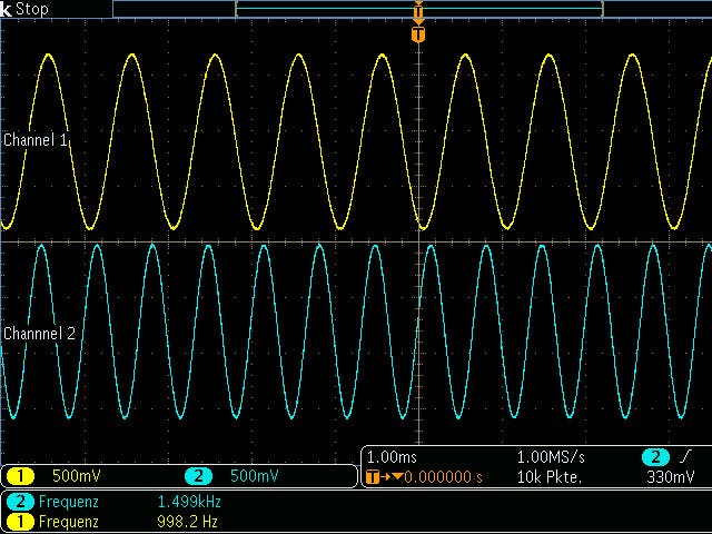
[INFO] Finished!Or with stereo audio:
-----------I2S Audio player-----------

[INFO] Looking for FIFO configuration...
[INFO] Initialize FIFO...
[INFO] Looking for GIC configuration...
[INFO] Initialize GIC...
[INFO] Setup interrupt handler...
[INFO] Enable exceptions...
[INFO] Enable FIFO interrupts...
[INFO] Initialize Clocking Wizard...
[INFO] Mount SD card...
[INFO] Opening file: Dual.wav...
        File size: 529208 bytes
        File format: 1
        Channels: 2
        Sample rate: 44100 Hz
        Bits per sample: 16 bits
        Block align: 4 bytes
        Data bytes: 264600 bytes
        Samples: 132300
        Use clock setting 1...
[INFO] Finished!


Comments