

Hardware components | ||||||
 |
| × | 1 | |||
 |
| × | 1 | |||
 |
| × | 1 | |||
| × | 1 | ||||
| × | 1 | ||||
Software apps and online services | ||||||
 |
| |||||
Hand tools and fabrication machines | ||||||
 |
| |||||
 |
| |||||
 |
| |||||
 |
| |||||
 |
| |||||
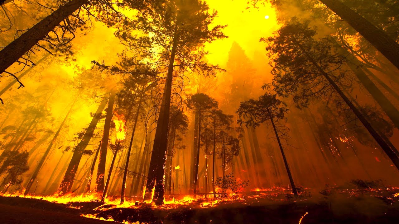
Fire Fighting Safety Issues
https://www.nifc.gov/safety/safety_documents/Fatalities-by-Year.pdf
The problem and safety concern is the Burnover problem. as you can see by the attached link and PDF is Burnover is a major cause of death and injury for fire fighters. Burnover is when a fire changes direction and goes over the heads of fire Fighters. This causes Burns, Asphyxiation and death.
the Following article in the firehouse.com website explains what happens when a fire changes directions https://www.firehouse.com/lodds/news/10460154/sd-firefighter-killed-4-others-hurt-in-burnover
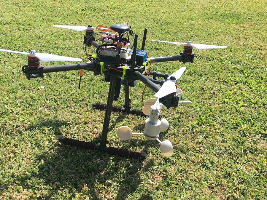
My solution utilizes a Particle LTE Microcontroller/ Wind Direction and speed Sensors / Air Quality Sensor / Smoke Sensor /Temperature and Humidity Sensor as well as a thermal camera . I am also developing a Satellite version for commercial deployment for areas without LTE coverage.
The Theory of Operation
* Drone will be deploy able by the fire fighters on the ground when they enter a fire zone area.
*Drone will be deployed to a high spot whether it is on a hill side or onto a tree top or a buildings roof.
* Once deployed instant analytics are uploaded to the cloud where the fire fighters can be alerted to temperature and humidity changes wind direction and speed as well as having a camera overview of the situation.
* Real time alerts and information of the on ground conditions will allow for quick decision making and safety escape routes .
*More than 1 drone can be deployed in a given area giving triangulation data for a better overview of speed and direction of the fire.
Benefits
Low cost as compared to helicopter deployment or fire-watch.
Disposable if lost in a fire or destroyed by accident
Different variations available for longer term deployment and fire prevention and warning.
Contest Variation: Quick deploy system with separate sensor and solar power sensor system with LTE Cloud connectivity High Speed Camera to watch for hot spots for close Suburban Proximity to assets and People.
Variation 1. 100% Solar Powered and Satellite Connected deploy able by GPS location. Long term sensor solution separate from Flying circuit for Forest and Mountain deployment where LTE is not available.
Variation 2. 100% Solar Powered LTE Connected Sensor system separate from Flying circuit. Deploy able to Suburban areas with LTE Connectivity for early warning of potential fire conditions(Low Humidity / High Temperature /High wind scenarios)
The Drone and Parts used in the Build
Whether you're an agriculturalist, a professional meteorologist or a weather hobbyist, building your own weather station can be a really rewarding project. When you're measuring weather, however, you need some pretty specialized sensors. This kit represents the three core components of weather measurement: wind speed, wind direction and rainfall.
None of the sensors in this kit contain active electronics, instead they use sealed magnetic reed switches and magnets so you'll need to source a voltage to take any measurements. The positive side of this is that the sensors are easy to read.
Sparkfun Sensors
Sparkfun VOC/O2 Sensor
Sparkfun Smoke Sensor
Sparkfun Temperature Humidity Sensor
Lightning Detector
Particle Electron LTE
https://store.particle.io/collections/cellular/products/electron-3g-americas
The Build
I mocked up the first initial build not tightening up anything to get an idea as to the complexity and difficulty of the build as well as making note as to where everything goes and to see if I need to make any changes to my design And to make note of any other tools I may need .
After I took the wold drone apart and Used nail polish on all screws and bolts ..
Image 1: I used Double tape on the Pads for the Voltage controllers for the fan motors as it provided a bit of room and padding. I also unscrewed and used Nail polish in the silver screws in the picture before torquing them back down..
Image 2: I used some extra double sided tape( but left the red covering on ) on the sides of the voltage controllers to prevent wearing on the controllers from wiring or the Motor Support tubes.
Image 3: Image shows the Nail Polish on the bottom screws of the motor Mounts.
Image 4: This Image is of the Drone Leg Mounts with the Nail Polish on the Back side and all they way through.
Image 6: I tye wrapped the Motor power feed down and used some double backed tape on the back of the controller to keep it in one spot for now.
PCB Build
I Had my Boards manufactured and Built by QUINT Tech Hong Kong LTD.
contact Freya at freya@quint-tech.com for a great Quote at Fantastic Pricing for a complete build.
This PCB can be mounted directly above the NXP Controller using 1" standoffs.
It has plug-ins for the above sensors as well as a separate control board for using where there is no LTE communications but there is LoRa. The separate detachable board has a SAMD21G18 series Chip and is Arduino Programmable using the MAKRWAN1300 Board Drivers and Program .
BOM
Attached
Programming
The programming of these boards is in 2 parts. 1 is the Particle programming witch will send sensor analytics to the cloud for alarms and location information. As well as temperature , humidity , VOC , CO , Smoke Intensity and Lightning distances and intensity..
Particle Programming
Adding the NXP temperature Sensor
NXP Drone Programming
First Follow the Instruction in the Following Link
https://nxp.gitbook.io/hovergames/downloads#rddrone-fmuk66-px4-bootloader
Once bootloader is installed you should see this in your Devices
Monitoring and Logging the Information
The Dashboard where the Fire conditions can be monitored
Adding the NXP IR temperature Sensor
I added the IR sensor to the front of the Drone and routed the wiring through one of the tubes.
// This #include statement was automatically added by the Particle IDE.
#include <Adafruit_MLX90614.h>
#include <SF_CCS811.h>
#include <Adafruit_BME280.h>
#include "MAX30105.h"
#include <SPI.h>
#include <Wire.h>
#include "SparkFun_AS3935.h"
#define AS3935_ADDR 0x03
#define INDOOR 0x12
#define OUTDOOR 0xE
#define LIGHTNING_INT 0x08
#define DISTURBER_INT 0x04
#define NOISE_INT 0x01
//======================================
#define BME_SCK D4
#define BME_MISO D3
#define BME_MOSI D2
#define BME_CS D5
#define SEALEVELPRESSURE_HPA (1013.25)
//======================================
uint32_t lastReset = 0;
#define CCS811_ADDR 0x5B //Default I2C Address
//#define CCS811_ADDR 0x5A //Alternate I2C Address
CCS811 mySensor(CCS811_ADDR);
//======================================
Adafruit_MLX90614 mlx = Adafruit_MLX90614();
//======================================
Adafruit_BME280 bme; // I2C
unsigned long delayTime;
unsigned long duration;
//=======================================
SparkFun_AS3935 lightning(AS3935_ADDR);
MAX30105 particleSensor;
const int lightningInt = 4;
int intVal = 0;
int noise = 5; // Value between 1-7
int disturber = 10; // Value between 1-10
//======================================
long startTime;
long samplesTaken = 0; //Counter for calculating the Hz or read rate
//=================**WeatherVane**=====================
int button = A4;                   // button is connected to D0
int LED = D7;                      // LED is connected to D1
int val = 0;
//========================================
unsigned long timeSinceLastTick = 0;
unsigned long lastTick = 0;
String windDir = "";
float windSpeed = 0;
long secsClock = 0;
#define WIND_SPD_PIN A4
#define WIND_DIR_PIN A5
#define AIR_RST      4
#define AIR_WAKE     15
#define DONE_LED     7
//============================================
void setup() {
Serial.begin(9600);
Wire.begin();
lastReset = millis();
//======================================
pinMode(LED, OUTPUT);            // sets pin as output
pinMode(button, INPUT_PULLDOWN); // sets pin as input
pinMode(A4, INPUT_PULLDOWN);
pinMode(WIND_SPD_PIN, INPUT_PULLDOWN);     // Wind speed sensor
attachInterrupt(digitalPinToInterrupt(WIND_SPD_PIN), windTick, FALLING);
//=========================================
Serial.println("MAX30105 Basic Readings Example");
particleSensor.begin();
particleSensor.setup(); //Configure sensor. Use 6.4mA for LED drive
byte ledBrightness = 255; //Options: 0=Off to 255=50mA
byte sampleAverage = 2; //Options: 1, 2, 4, 8, 16, 32
byte ledMode = 3; //Options: 1 = Red only, 2 = Red + IR, 3 = Red + IR + Green
int sampleRate = 50; //Options: 50, 100, 200, 400, 800, 1000, 1600, 3200
int pulseWidth = 118; //Options: 69, 118, 215, 411
int adcRange = 4096; //Options: 2048, 4096, 8192, 16384
particleSensor.setup(ledBrightness, sampleAverage, ledMode, sampleRate, pulseWidth, adcRange); //Configure sensor with these settings
particleSensor.enableDIETEMPRDY();
startTime = millis();
//=======================================
bme.begin();
mySensor.begin();
Adafruit_MLX90614 mlx = Adafruit_MLX90614();
//========================================
pinMode(lightningInt, INPUT);
Serial.println("AS3935 Franklin Lightning Detector");
if( !lightning.begin() ) { // Initialize the sensor.
Serial.println ("Lightning Detector did not start up, freezing!");
while(1);
}
else
Serial.println("Schmow-ZoW, Lightning Detector Ready!");
lightning.setIndoorOutdoor(OUTDOOR);
//=======================================
}
void loop() {
char message1[120];
char message2[120];
char message3[120];
char message4[128];
char message5[128];
if (millis() - lastReset > 5*60000UL) {
//    System.reset();
}
//======================================
static unsigned long outLoopTimer = 0;
static unsigned long clockTimer = 0;
static unsigned long tempMSClock = 0;
tempMSClock += millis() - clockTimer;
clockTimer = millis();
while (tempMSClock >= 1000)
{
secsClock++;
tempMSClock -= 1000;
}
Serial.print("Wind dir**: ");
windDirCalc(analogRead(WIND_DIR_PIN));
Serial.print("  ");
Serial.print(windDir);
Serial.println(" Degrees ");
//==================================================================
int WindVolts;
analogRead(WIND_DIR_PIN);
WindVolts=(WIND_DIR_PIN);
Serial.print("WindVolts ");
Serial.println(WindVolts);
if (WindVolts < 1.50) windDir="202.5"; {
if (WindVolts < 1.4) windDir = "180";
if (WindVolts < 2.93) windDir = "247.5";
if (WindVolts < 3.08) windDir = "225";
if (WindVolts < 3.0) windDir = "292.5";
if (WindVolts < 3.1) windDir = "270";
if (WindVolts < 0.32) windDir = "112.5";
if (WindVolts < 0.90) windDir = "135";
if (WindVolts < 3.2) windDir = "337.5";
if (WindVolts < 3.3) windDir = "315";
if (WindVolts < 0.41) windDir = "67.5";
if (WindVolts < 0.45) windDir = "90";
if (WindVolts < 1.98) windDir = "22.5";
if (WindVolts < 2.25) windDir = "45";
if (WindVolts < 3.25) windDir = "0";
Serial.print("WindDIR ");
Serial.println(windDir);
Particle.publish("windDir",windDir, PRIVATE);
delay(10000);
}
//==================================================================
if (timeSinceLastTick != 0) windSpeed = 1000.0/timeSinceLastTick;
Serial.print("Windspeed: ");
duration = pulseIn(A4, LOW);
timeSinceLastTick = 0;
Serial.print(windSpeed*1.94);
Serial.print(" mph ");
Serial.print(windSpeed*2.4);
Serial.println(" kph ");
delay(10);
//=====================================
val = pinReadFast(button);       // read the input pin
digitalWriteFast(LED, val);
delay(1);
duration = pulseIn(A4, HIGH);
// Serial.printlnf("%d us", duration);
//==================**BME280**====================
Serial.print("Temperature = ");
Serial.print(bme.readTemperature());
Serial.print(" *C ");
Serial.print("Pressure = ");
Serial.print(bme.readPressure() / 100.0F);
Serial.print(" hPa ");
Serial.print("Approx. Altitude = ");
Serial.print(bme.readAltitude(SEALEVELPRESSURE_HPA));
Serial.print(" m ");
Serial.print("Humidity = ");
Serial.print(bme.readHumidity());
Serial.print(" % ");
Serial.println();
//========================**MAX30105***===============================
samplesTaken++;
Serial.print(" R[");
Serial.print(particleSensor.getRed());
float RED = particleSensor.getRed();
Serial.print("] IR[");
float IR = particleSensor.getIR();
Serial.print(particleSensor.getIR());
Serial.print("] G[");
float GRN = particleSensor.getGreen();
Serial.print(particleSensor.getGreen());
Serial.print("] Hz[");
Serial.print((float)samplesTaken / ((millis() - startTime) / 1000.0), 2);
Serial.print("]");
float temperature = particleSensor.readTemperature();
Serial.print("temperatureC=");
Serial.print(temperature, 4);
Serial.println();
particleSensor.nextSample(); //We're finished with this sample so move to next sample
//=======================**Lightning***================================
if(digitalRead(lightningInt) == HIGH){
byte distance = lightning.distanceToStorm();
Serial.print("Approximately: ");
Serial.print(distance);
Serial.println("km away!");
sprintf(message3,"KM %s",distance);
//      Particle.publish("String3", message3, PRIVATE);
intVal = lightning.readInterruptReg();
if(intVal == NOISE_INT){
Serial.println("Noise ");
sprintf(message3,"Noise %s",distance);
//      Particle.publish("String3", message3, PRIVATE);
}
else if(intVal == DISTURBER_INT){
byte distance = lightning.distanceToStorm();
Serial.print("Approximately: ");
Serial.print(distance);
Serial.println("km away!");
sprintf(message3,"KM %s",distance);
Particle.publish("String3", message3, PRIVATE);
Serial.println("Disturber.");
sprintf(message3,"Disturber %d",distance);
//      Particle.publish("String3", message3, PRIVATE);
}
else if(intVal == LIGHTNING_INT){
Serial.println("Lightning Strike Detected!");
byte distance = lightning.distanceToStorm();
Serial.print("Approximately: ");
Serial.print(distance);
Serial.println("km away!");
sprintf(message3,"KM %d",distance);
//     Particle.publish("String3", message3, PRIVATE);
}
}
//===============================**CCS811**==============================
mySensor.readAlgorithmResults();
Serial.print("CO2[");
Serial.print(mySensor.getCO2());
Serial.print("] tVOC[");
Serial.print(mySensor.getTVOC());
Serial.print("]");
Serial.println();
//========================================================================
Serial.print("Ambient = "); Serial.print(mlx.readAmbientTempC());
Serial.print("*C\tObject = "); Serial.print(mlx.readObjectTempC()); Serial.println("*C");
Serial.print("Ambient = "); Serial.print(mlx.readAmbientTempF());
Serial.print("*F\tObject = "); Serial.print(mlx.readObjectTempF()); Serial.println("*F");
Serial.println();
sprintf(message2,"CO2%d,TVOC%d,WNDSP%.2f,RED%.2f,IR%.2f,GRN%.2f,IR_TMP%f,Ambient%.2f,tObject%.2f",mySensor.getCO2(),mySensor.getTVOC(),(windSpeed*2.4),RED,IR,GRN,temperature,mlx.readAmbientTempC(),mlx.readObjectTempC());
sprintf(message1,"BME_TMP%.1f,BME_PRESS%f,BME_ALT%.2f,BME_HUM%.2f",bme.readTemperature(),(bme.readPressure() / 100.0F),(bme.readAltitude(SEALEVELPRESSURE_HPA)),bme.readHumidity());
sprintf(message4,"%d,%d,%.2f,%.2f,%.2f,%.2f,%.2f,%.1f,%f,%.1f,%.2f,%.2f,%.2f",mySensor.getCO2(),mySensor.getTVOC(),(windSpeed*2.4),RED,IR,GRN,temperature,(bme.readTemperature()),(bme.readPressure()/100.0F),(bme.readAltitude(SEALEVELPRESSURE_HPA),(bme.readHumidity(),mlx.readAmbientTempC(),mlx.readObjectTempC())));
sprintf(message5,"%d,%d,%.2f,%.2f,%.2f,%.2f,%f,%.1f,%f,%.2f,%.2f",mySensor.getCO2(),mySensor.getTVOC(),(windSpeed*2.4),RED,IR,GRN,temperature,bme.readTemperature(),(bme.readPressure() / 100.0F),(bme.readAltitude(SEALEVELPRESSURE_HPA)),bme.readHumidity());
Particle.publish("String5", message5 , PRIVATE);
Particle.publish("String2", message2 , PRIVATE);
Particle.publish("String1", message1 , PRIVATE);
Particle.publish("String4", message4 , PRIVATE);
//========================================================================
delay(10000); // Slow it down.
}
//========================================================================
//========================================================================
//========================================================================
//========================================================================
//========================================================================
void windTick(void) {
timeSinceLastTick = millis() - lastTick;
lastTick = millis();
}
void windDirCalc(int vin) {
if      (vin < 1.50) windDir="202.5";
else if (vin < 1.4) windDir = "180";
else if (vin < 2.93) windDir = "247.5";
else if (vin < 3.08) windDir = "225";
else if (vin < 3.0) windDir = "292.5";
else if (vin < 3.1) windDir = "270";
else if (vin < 0.32) windDir = "112.5";
else if (vin < 0.90) windDir = "135";
else if (vin < 3.2) windDir = "337.5";
else if (vin < 3.3) windDir = "315";
else if (vin < 0.41) windDir = "67.5";
else if (vin < 0.45) windDir = "90";
else if (vin < 1.98) windDir = "22.5";
else if (vin < 2.25) windDir = "45";
else if (vin < 3.25) windDir = "0";
else windDir = "0";
}
Alerts
Temperature change / Humidity/ Wind Direction /Wind Speed alerts can be programmed in to send an SMS message, Email , Or sound an alarm
The Easiest way to do this is to program it into Node Red and send an SMS message when there is a change of wind Direction and / Or Speed
Go to Twilio https://www.twilio.com/ Sign up and configure your Account And configure the Twilio Node in Node red
Conclusion
There are a few things I am going to add to the drone when I have more money is a camera System for search and rescue and more sensor capability including a long range Flame sensor (In Production now)
Final Build Pictures
Final Build Cost
3D Print
I designed my Case with Fusion_360 its an excellent drawing program for making boxes etc for my projects
I wanted the Box to be Spray resistant but still let air through the vents for monitoring the Air quality and be sleek and aerodynamic a little bit as well.
Detailed Build Cost
Drone and Controller $356.00
Camera System $125.96
Battery $25.00-$45.00
Raspberry Pi4 2Gig $79.99
Air Speed Sensor $75.00
Wind Direction Sensor $66.90
Sub Total $728.85
PCB Build Cost Per Board
PCB $5.00
PCB Parts $65.86
Shipping $20.00
3D Box Build Cost
ProtoLabs $253.00
Other Parts
Particle Electron $65.00
Solar Panel $
Wiring,Nuts and Bolts $25.00
Misc Parts and Pieces
Resources (the following links were used in the design and production of this entry)not in any particular order of importance.
https://cportal.protolabs.com/myaccount/en-US/quote/modify.do?quoteId=772935&contactId=132134
https://i.ytimg.com/vi/bhvjfC5qenQ/maxresdefault.jpg
https://www.firehouse.com/lodds/news/10460154/sd-firefighter-killed-4-others-hurt-in-burnover
https://theintegralschoolblogdotorg.files.wordpress.com/2016/12/forest-fires-1.jpg
https://nxp.gitbook.io/hovergames/

Comments