
Hardware components | ||||||
| × | 1 | ||||
| × | 2 | ||||
| × | 1 | ||||
| × | 2 | ||||
| × | 1 | ||||
| × | 1 | ||||
| × | 1 | ||||
Software apps and online services | ||||||
| ||||||
 |
| |||||
| ||||||
Hand tools and fabrication machines | ||||||
 |
| |||||
I got captured by this fun world of making of badges, it's addictive.
When I see a characters I just imagine how I could adapt it to make them a pin badge.
Autobots, roll out.
IdeaThis time was trying to do something with reverse mount LEDs, not every character could afford this, some of them look weird and diabolic :P, but this caught my attention after watching the movie and the camaros' emblem.
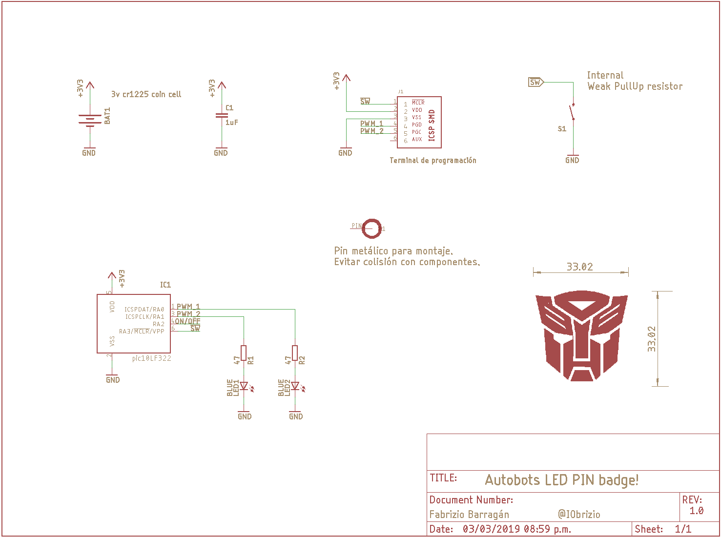
FunctionalityI've applied the knowledge gained with the previous badges improving the design, I maintained the hardware basis, a PIC10LF322 as the circuit's heart, this little PIC just has 4 GPIOS and one of them it's only input.
Now I use the MCU's low power features, I discard the extra hardware to turn ON/OFF, this change simplify the design and let me explore how to minimize the power consumption.
The LEDs are controlled by the PWM module, the clock source is the internal oscillator and the button its attach to external interrupt.
The design does not allow to use a CR2032 battery so I had to use a smaller size, a CR1220 battery.
- This pin #badge uses a 3v battery CR1216/25
- The PIC10LF322 MCU keeps in SLEEP mode reducing the power consumption
- Wake up the MCU pressing the button
- PWM at 1KHz 8bits x 2 LEDs
- Pull-up resistor + Button
- Int RC oscillator 500KHz
- #LED reverse mounted
The PCB profile was made faster than before, I use Inkscape to draw the Autobots image, it was helpful to separate the layers too. Once I had the profile it was exported as DXF.
I've been using Autodesk EAGLE for a while, it's easy and faster, check what you could do.
It's fast and easy with Autodesk Fusion 360 importing the profile made with inkscape.
- Import the picture into Autodesk Fusion 360
- Scale it to wanted size
- Make it a PCB
- Pull PCB from Eagle
- Now you get the dimension layer, a close profile
- To finish just PUSH your PCB to update the Autodesk Fusion 360 model
Set PCB restrictions with polygons or use the layers previously separated on Inkscape.
No copper and no solder mask. This way you expose the bare material, mainly FR4.
You can solder this board manually .The complex part is the MCU, but you'll be ok.
Check out these videos on how it was assembled:
ProgrammingThe code almost fill the memory space, 93% XD,The cpu clock is set up at 500KHz, it can go faster up to 16MHz but theres no need.
On the back side there is the ICSP terminal, 0.1inch pitch. I used pogo pins, they are really comfortable.
How It LooksJust press the push button on the backside to turn on and change between flashing patterns.
Press again to turn off.
How to Get One?
I have a some of them, send me a message or check at tindie Store.
I'm on twitter, you can see what's going on @IObrizio.
I hope you enjoy this gadget! :-D
Thank you, best regards!


_t9PF3orMPd.png?auto=compress%2Cformat&w=40&h=40&fit=fillmax&bg=fff&dpr=2)


Comments