


Hardware components | ||||||
 |
| × | 1 | |||
Imagine this: you drive up to your gate, and it opens automatically — no remote, no app, no subscription. With our Gate module, that’s not science fiction but a weekend project any maker can build.
Gate is a battery-capable, offline license-plate recognition (ANPR) opener based on the Himax HX6538 (Cortex-M55 + Ethos-U) vision MCU and an nRF52833 controller. It uses a ToF sensor to wake the vision processor only when a vehicle approaches and performs all recognition locally — no cloud, no monthly fees.
Original project: https://www.hackster.io/Grovety/gate-offline-license-plate-recognition-gate-opener-1812df.
This continuation focuses on a specific, practical integration: how to make Gate operate any existing barrier or gate without modifying the gate’s controller by emulating a button press on the gate remote (the “remote-key integration” approach).
How it works in practiceWhen a vehicle approaches, the ToF sensor wakes the Gate module and the camera captures the plate. The Vision MCU (HX6538) detects and decodes the plate characters and sends the result to the nRF52833 controller. The nRF checks this text against its local whitelist.
- If the plate is authorized, the nRF outputs a short 3.3 V pulse. This drives the optocoupler, which momentarily shorts the button pads on the spare gate remote — exactly as if the user pressed the remote button. The remote transmits its RF signal, and the barrier opens.
- If the plate is not in the whitelist, no GPIO pulse is generated, the remote is not triggered, and the barrier remains closed.
Gate uses a two-brain embedded architecture. The Vision MCU (Himax HX6538) runs tiny neural networks (plate detection + plate OCR) locally via TFLite Micro and the Ethos-U accelerator; the nRF52833 acts as the low-power manager and communication controller. A ToF sensor is polled by the nRF in sleep mode; when it detects an approaching object, the nRF powers on the Vision MCU and camera. The Vision MCU then captures a frame, detects any license plate, decodes the characters, and sends the resulting text to the nRF (over SPI/UART). The nRF checks the text against a stored whitelist and — if authorized — toggles an output that simulates the gate-remote button press to open the barrier. After the action, the Vision MCU and camera are powered down, and the device returns to low-power standby.
Why use the remote-button approachBefore wiring anything, it is helpful to understand why connecting to an existing spare remote is often the preferred method:
- Non-invasive: No need to open the gate motor controller or touch factory wiring — keeps warranties intact and eliminates risk of damaging the motor electronics.
- Universal compatibility: Almost all modern gate motors respond to a simple momentary contact closure — simulating the remote button works with nearly any system.
- Safety & reversibility: If something goes wrong, you can simply disconnect the remote harness, and the gate resumes normal operation.
- Simplicity: The approach requires only a pair of wires, making it suitable for quick deployments.
- Maintainability: Remote remains physically available as a fallback; remote-key hack is easy to revert or update.
Minimal recommended parts for the remote-key integration:
- Gate module (the Grovety/ELECROW Battery-Powered Edge AI Module with HX6538 + nRF52833) — 1 pc.
- A spare gate remote (existing RF fob) with a mechanical pushbutton you can access. If you don’t have a spare, any compatible RF transmitter module or spare remote work.
- Optocoupler module or small relay board (for galvanic isolation) — e.g., a 4-pin optocoupler or a 1-channel solid-state relay suitable for low-voltage logic. Use an optocoupler for best isolation and longevity when simulating dry contacts. (Recommend: use an optocoupler rated for low-voltage DC and with an open-collector / isolated output.)
- Small signal NPN transistor or MOSFET (optional) if you prefer to drive the optocoupler via a transistor stage; many opto modules are directly TTL-driveable by nRF GPIO.
- Thin, flexible insulated wires (26–28 AWG) for soldering onto remote PCB.
- Crimp pins or JST connectors (to route the wires into a small outdoor enclosure).
- Heat-shrink tubing and silicone glue for mechanical strain relief and moisture protection.
- Small enclosure (weatherproof if mounting outdoors) or CCTV camera housing if you plan permanent installation.
- Power supply: 5V USB supply for bench tests; for field installation, use the recommended battery pack / Li-Po + step-up as per theoriginal Gate spec.
- Multimeter, small soldering iron (low wattage for small SMD pads), and ESD precautions.
Optional but recommended:
- Small LED (to visually indicate when the Gate issues a “press” signal during commissioning).
- Test jig (two-pin header) so you can test the optocoupler/relay before soldering to the remote.
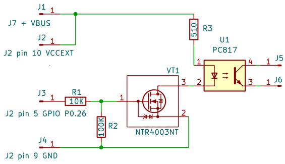
The integration is straightforward: we simulate a momentary push of the remote’s button using an isolated electronic switch. The Gate module drives a GPIO pin on the nRF52833; this GPIO activates an optocoupler (or relay), which in turn closes the circuit across the button pads of the remote.
Connections (recommended):
- Gate module GPIO: P0.26 (header J2-5).
- Ground: J2-9.
- 3.3V supply: J7-1 (if powering the optocoupler from module VCC).
- Remote button pads: two soldered wires connected across the original button contacts.
Flow: GPIO HIGH → optocoupler LED on → transistor closes → remote button circuit shorted → RF signal transmitted.
1. Open the remote enclosure carefully with a plastic pry tool. Avoid damaging the clips.
2. Identify the button pads (two contacts for the OPEN button).
3. Tin and solder thin insulated wires (26–28 AWG) to each pad. Keep solder joints small; avoid bridging.
4. Route wires through a small hole in the case or via the battery compartment edge. Add strain relief (hot glue + heat-shrink).
5. Reassemble the remote, ensuring no wires are pinched and the battery still fits.
6. Connect the wires to the optocoupler output pins in your small interface board.
Tips:
- Use a low-wattage iron and fine solder.
- Keep heat under 2–3 seconds per pad to avoid lifting traces.
- Test the remote after soldering — the button should still work manually.
What you’ve just seen isn’t only a clever hack for a toy barrier. The same Gate module can power a real upgrade at your own garage, driveway, or even a shared parking lot. Because all plate recognition and access checks run locally, you stay in control: no vendor lock-in, no cloud delays, no hidden fees: just your whitelist and your rules.
With only a spare remote and a few minutes of soldering, you can turn this project into a working product — one that greets you automatically every time you drive up. And once you build it, the ideas keep coming:
- log arrivals and departures,
- trigger lights or cameras when the car is recognized,
- experiment with new AI models to make it smarter.
That’s the beauty of an open, modular platform: you start with a working gate opener and grow it into whatever you imagine.
We are planning to release an API that will allow users to switch to recognizing their own local license plates in cases where our neural network may not identify them.
Currently, this can only be done manually with our assistance.
If you are interested, feel free to contact us at hi@grovety.com
👉 Ready to try it? Grab the base module on Elecrow, follow this guide, and watch as your garage door opens itself.
And please share your builds — your feedback and ideas will shape the next firmware updates and community projects.
References & LinksOriginal Hackster project (full build guide and background): 👉 Gate – Offline License Plate Recognition Gate Opener
Product page on Elecrow (Edge AI Module, base hardware): 👉 Himax HX6538 Edge AI Module on Elecrow
GitHub repository (firmware, ANPR models, integration examples): 👉 Grovety / himax_gate
Related ProjectsExplore more DIY AI builds from our team:


Comments