

Hardware components | ||||||
| × | 1 | ||||
| × | 1 | ||||
_wzec989qrF.jpg?auto=compress%2Cformat&w=48&h=48&fit=fill&bg=ffffff) |
| × | 1 | |||
 |
| × | 1 | |||
| × | 1 | ||||
| × | 1 | ||||
Software apps and online services | ||||||
 |
| |||||
| ||||||
This story began at the moment when we got the need of an RF signal source for our experiments with SDR radio. For us were important parameters such as: high stability of frequency, low level of phase noise and also the minimal number of harmonics and spurious. Naturally, when working with SDR radio, it was necessary the ability of quick and easy adjustment of the output frequency in a wide range, for example, from 100 kHz to 500 MHz.
For implementing that kind of task, the DDS method (Direct Digital Synthesis) is ideally suitable. There existing ready-made IC (Integrated Circuits) for DDS on the market, here are the most common ones among them from Analog Devices IC: AD9910, AD9912, AD9914 and AD9915. We opted for the AD9910 because it has all the qualities we needed and it has a fair price.
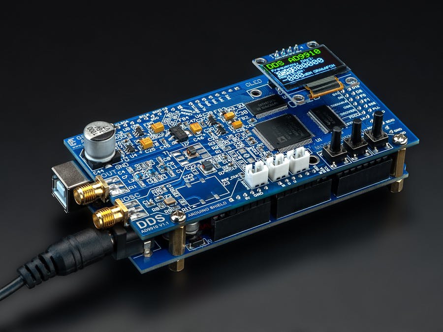
The original branded Evaluation Board costs more than 600 USD. Therefore we decided to first look for a Chinese clone of such a board and it was easily found and bought on eBay at a price of 70 USD:
When the Chinese copy came to us, it turned out that there is no any existing software for it, and the seller could not provide for us even a connection diagram! It was sad that even an Internet search did not gave an answer on how is it to connect the Chinese board to the microcontroller. It took us for 3 full working days to redraw the circuit of this board on paper. This task was complicated by the fact that the board was of black color and the printed conductors were very poorly visible on it.
After the circuit was composed and before the first start-up, we decided to measure and check the ratings of some elements that caused us a suspicion and it turned out that elements with incorrect ratings were installed in the PLL Loop Filter circuit. We had to recalculate them according to the datasheet for the AD9910 (p. 26) and replace them with the correct ones. Upon further inspection of the Chinese board, it turned out that there were short circuits between several AD9910 legs (made by the Chinese worker during the assembly of this board), and one leg was not soldered at all. Naturally, all these shortcomings had to be eliminated before the first start-up.
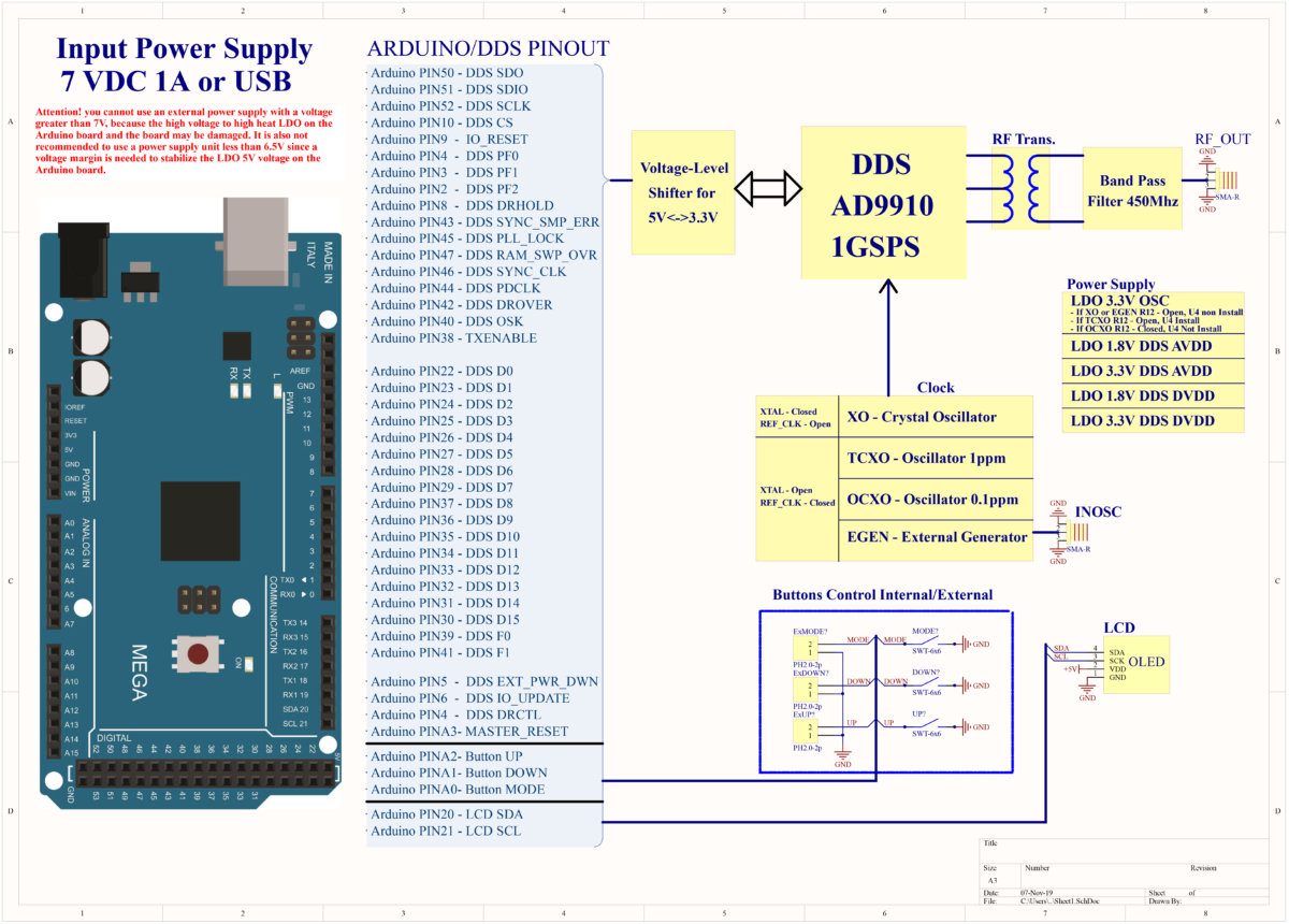
Next came the stage of connecting to the microcontroller. In order not to create unnecessary difficulties when programming as a controller for controlling the AD9910, we chose the Arduino Mega. But since the ATmega2560, which is installed on the Arduino Mega, has signal levels of 5 Volts, and the AD9910 has 3.3 Volts, it had to also connect an additional level converter for 32 channels.
After that it had to study the datasheet for the AD9910 and write a control program. And only after that it was possible to turn on this whole circuit and measure the output signal. It is better to do all this with a spectrum analyzer. When we turned on the spectrum analyzer, we were unpleasantly surprised at how terrible everything was:
There were a lot of harmonics and spurious on the screen, and their level reached -25 dBm! And this is despite the fact that according to the documentation by Analog Devices to AD9910 the level of harmonics should not exceed -60 dBm. This was already enough to understand that nothing good would come out of using this board as a heterodyne for an SDR receiver. But we decided on practice to make sure on how badly everything will be.
To receive the signal, we used a receiver based on the IC MC3362, and fed the RF signal from the DDS AD9910 to the heterodyne input of the MC3362, and the Yaesu VX-6R radio station was used as a transmitter. But despite the high-quality transmitter, we could not hear anything except noise and screeching.
Therefore, we set a goal to create a generator with the characteristics declared in Datasheet and Applications Notes to the AD9910 in the form of a Shield for Arduino, that is, with the ability of connection without extra wires and external peripheral circuits, such as level converters.
Upon creating such Shield, we strictly adhered to all the recommendations from the manufacturer, and did some things even better. Here is an incomplete list of the main technical solutions that allowed us to achieve a good result at the end:
- In accordance with the recommendation from Analog Devices, we used a 4-layer board, not a 2-layer one, as the Chinese did to reduce the cost of production.
- Analog Devices recommends making separate or separate the power lines of analog circuits and digital ones with FB (Ferrite Beads), but we did even better: each power circuit is stabilized with a separate LDO (Low-Dropout Regulator) stabilizer and separated with FB.
- The power scheme itself was implemented in such a way that the device could be powered from both USB and an external 7 volt power source. IMPORTANT: not to use an external power source with a voltage above 7 volts, since the DDS is powered by linear stabilizers with a low level of ripples, but they can fail due to overheating if they are powered with a voltage above 7 volts. It is thanks to the correct wiring of the board, the presence on the board of high-quality stabilizers, tantalum capacitors and common capacitor with capacity of 1000 uF, that the DDS core could be overclocked to 1.5 GHz and this is with powered by USB!
- We found out that one of the reasons for the appearance of a large number of harmonics on the Chinese board is the DDS clock generator. The Chinese used a generator with a TTL output of 3.3 Volts. Such generator produces a rectangular signal with an infinite number of harmonics. Therefore, we used a generator with a clipped sine TCXO, since it has a minimal spectrum. And besides, it is more stable compared to the TTL generator.
- The next problem with the Chinese board was that when clocked from an external source, the input signal passed through an ordinary jumper, which is intended only for transmitting a low-frequency signal, but not for a signal with a frequency of 1 GHz! Therefore, for switching clock sources, we use feed-through capacitors that needs to be soldered to the appropriate place to connect the desired clock source.
- We connect all clock sources (except crystal) through balun in order to eliminate possible common-mode interference.
- We installed an output transformer on the +IOUT/-IOUT outputs of the AD9910 to suppress even harmonics and increase the output signal level by 3 dBm.
- We used the output filter already on the 7-th order, it was calculated and modeled in the AWR Microwave Office program, and the design and layout of the PCB section for this filter were taken from Application Notes AN-837 from Analog Devices.
In total, at this moment, the device has the following view:
- Form factor of Shield for Arduino Mega.
- Two high-speed level converters are installed on the board, which (in addition to control via the SPI bus) allows controlling DDS via parallel interface. Thus enables usage of all functions without unnecessary wires and connecting external circuits.
- The Shield is equipped with a 0.96” (or 1.54" in version 3.x ) detachable OLED Display.
There are 3 buttons on the device for control and navigation in the menu. (In the current version, they have been replaced with an encoder and an output on/off button.)
The software part of the device allows to configure and save the following parameters in non-volatile EEPROM memory:
- The output signal frequency from 100 kHz to 450 MHz (600 MHz during overclocking 1.5Ghz) with increment of 1 Hz.
- The amplitude of the output signal from 0 to -84 dBm (or from +4 when setting the DAC Current HI).
- Perform AM (Amplitude Modulation) with adjustment:
- frequency modulation from 10 Hz to 100 kHz.
- depths of modulation from 0% to 100%.
- Produce FM (Frequency Modulation) with adjustment:
- frequency modulation from 10 Hz to 100 kHz.
- deviations from 0 Hz to 100 kHz.
- You can configure the frequency change (Sweep) and set the period of this change
- New mode in version 3.x - S-Curve, This mode is essential for optimal tuning of a quadrature coil or for testing a ceramic discriminator in an FM detector:
- New mode in version 3.x - Local Oscillator: an ideal solution for use as a local oscillator in superheterodyne radio receivers due to its very low phase noise and high frequency stability:
- Select the clock source (XO, TXCO or external oscillator) and its frequency (In version 3.x, a hardware switch was added, enabling seamless switching between the following clock sources without the need to solder any components: TCXO, External TCXO/OCXO, or an external oscillator.):
- Overclock (adjust the core frequency) from 1000 MHz to 1500 MHz.
- Offset parameter allows adjusting the core clock frequency if the clocking deviation from the specified value is known
Starting with version 2.14, the ability to control via the serial port has been added.
- F - Set Frequency in Hz (100000 — 600000000)
- P - Set Output Power in dBm (-72 — 0 or -68 — +4, depending on "DAC current")
- E - Enable Output
- D - Disable Output
- M - Get Model
- V - Get Firmware Version
- h - Help
- ; - Commands Separator
Example:
F100000;P-2
Set Frequency to 100 kHz, and Output Power to -2 dBm.
Any number of commands in any order is allowed.
We took measurements of two boards and compared their readings:
Phase Noise:
Since the intrinsic phase noise of DDS is obviously less than that of PLL generators, the final value is highly dependent on the clock source. In order to achieve the values stated in the datasheet on AD9910, when designing our DDS AD9910 Arduino Shield, we strictly adhered to all recommendations from Analog Devices: PCB layout in 4 layers, separate power supply of all 4 power lines (3.3 V digital, 3.3 V analog, 1.8 V digital, and 1.8 V analog). Therefore, when buying our DDS AD9910 Arduino Shield, You can focus on the data from the datasheet on the AD9910.
Figure 16 shows the noise level when using the built-in PLL in DDS. The PLL multiplies the frequency of a 50 MHz generator by 20 times. We use a similar frequency - 40 MHz (x25 Multiplier) or 50 MHz (x20 Multiplier) from TCXO which gives even more stability.
And figure 15 shows the noise level when using an external reference clock 1 GHZ, with the PLL off.
Comparing these two plots, for example, for Fout = 201.1 MHz and the internal PLL turned on at 10 kHz carrier offset, the phase noise level is -130 dBc @ 10 kHz. And with the PLL off and using external clocking, the phase noise is 145 dBc @ 10kHz. That is, when using an external clock phase noise by 15 dBc better (lower).
For the same frequency Fout = 201.1 MHz, and the internal PLL turned on at 1 MHz carrier offset, the phase noise level is -124 dBc @ 1 MHz. And with the PLL off and using external clocking, the phase noise is 158 dBc @ 1 MHz. That is, when using an external clock phase noise by 34 dBc better (lower).
Conclusion: when using external clocking, You can get much lower phase noise than using the built-in PLL. But do not forget that in order to achieve such results, increased requirements are put forward to the external generator.
And since low-phase-noise 1 GHz oscillators are scarce in the market for some reason, we had to manufacture one ourselves. We named it RCLN1000.
Below are the brief technical specifications of what we have achieved:
Frequency: 100 kHz – 420 MHz (600 MHz*)
Spurs max: -60 dBc
Frequency step: 1 Hz
Output power: +0 dBm (+4**) to -84 dBm (on 50 Ohm load)
Output level up to: 1 Vpeak-to-peak (at +4 dBm)
Phase noise: -135 dBc/Hz @ 1 Khz offset (400 MHz Carrier)
Output filter: LPF LC 7th Order 600 MHz cut-off (-3 dB)
Modulation frequency for AM: 10 Hz to 100 kHz in 1 Hz step
AM modulation depth: 0% to 100% in 1% increments
Modulation Frequency for FM: 10 Hz to 100 kHz in 1 Hz step
FM modulation deviation frequency: 0 Hz to 100 kHz in 1 Hz step
Reference clock sources (on choice): XO-Crystal Oscillator, TCXO 1ppm, OCXO 0.1ppm, Crystek, or External Oscillator up to 1.5 Ghz
Power Requirements: USB or External Power Supply 7.5V DC 1A
Size: 53 x 102 х 32 mm
* When overclocking the core to 1.5 GHz
** When the “DAC Current HI” function is activated


Comments