// SKETCH: Ohmmeter_Autoranging_SimpleCircuitcom.ino
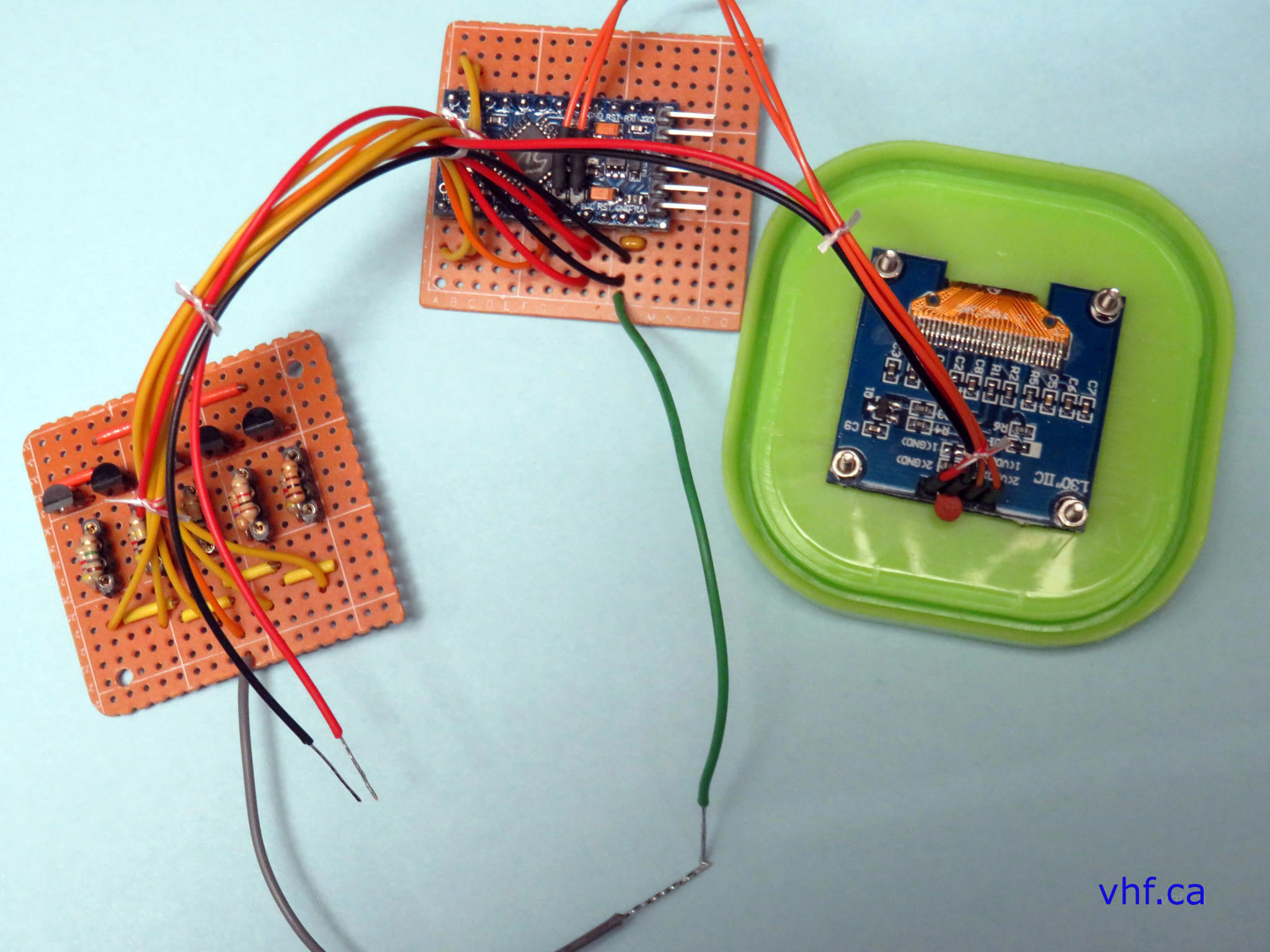
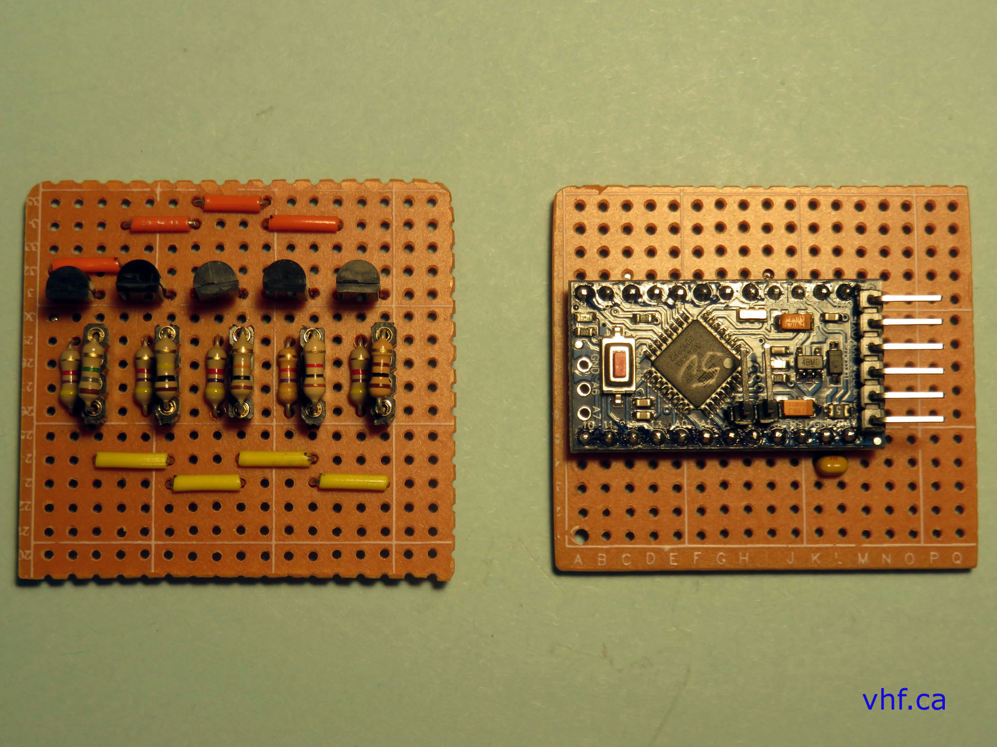
// Autoranging Ohmmeter with 128x64 Oled display with Arduino Pro-Mini
// SH1106 Oled display driven with I2C via A4=SDA & A5=SCK.
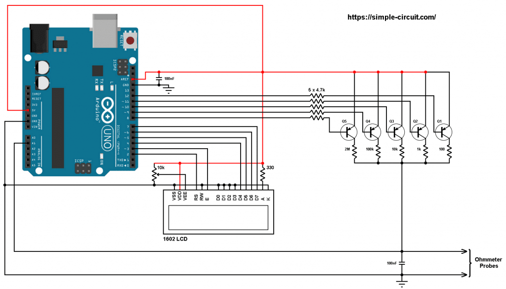
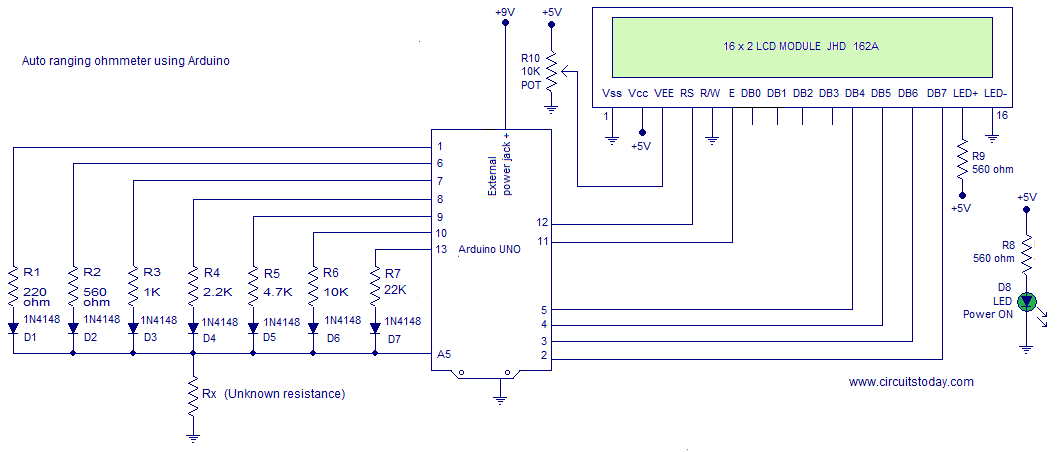
// Adaped from: https://simple-circuit.com/arduino-auto-ranging-ohmmeter-lcd/
#include <Arduino.h>
#include <U8g2lib.h> // Oled library
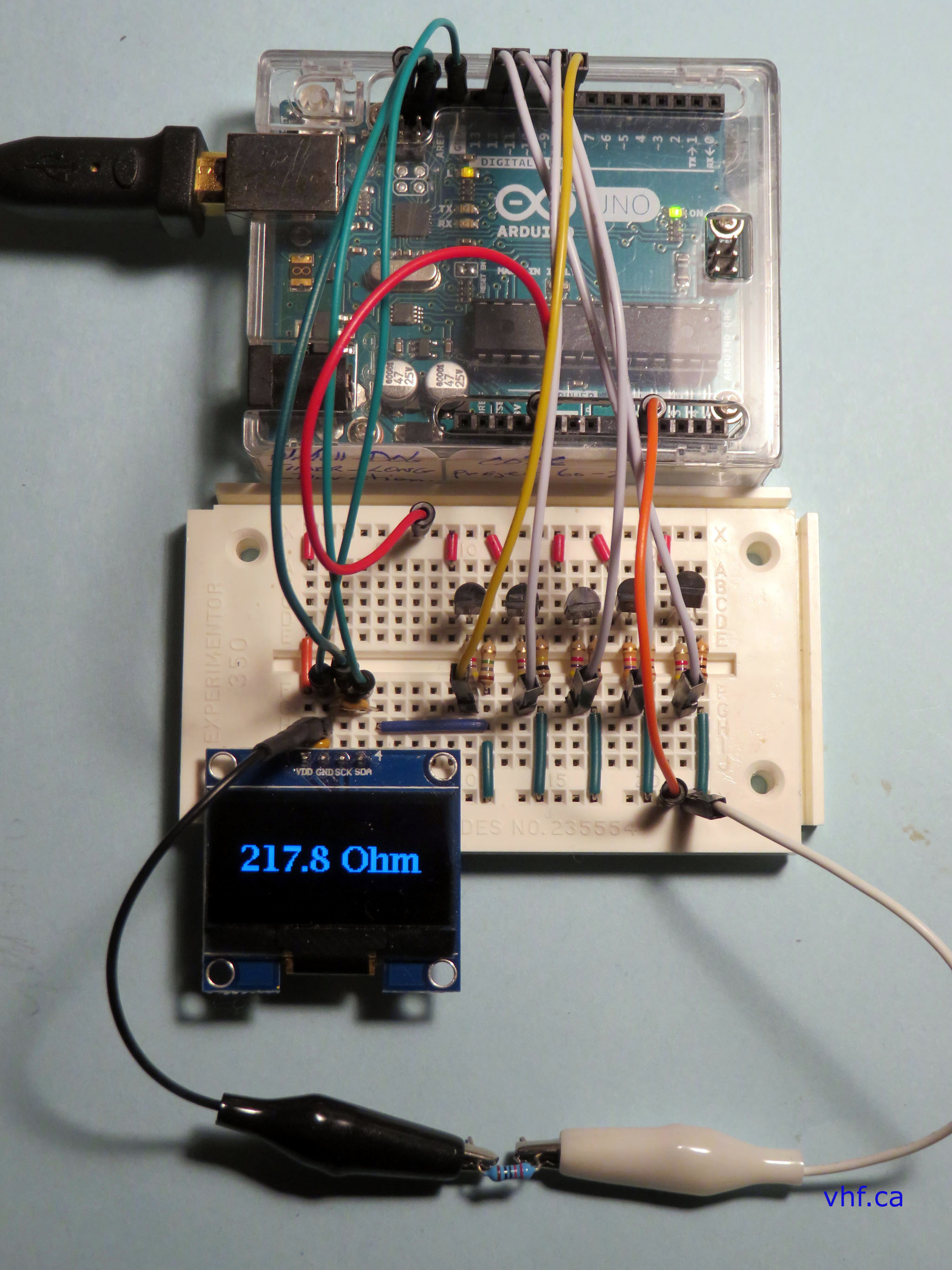
// Define digital pins to enable pnp transistors through 4k7 ohm base resistor
#define CH0 12 // Q1 - 100 ohm range
#define CH1 11 // Q2 - 1k ohm range
#define CH2 10 // Q3 - 10k ohm range
#define CH3 9 // Q4 - 100k ohm range
#define CH4 8 // Q5 - 1 Meg ohm range
byte ch_number;
uint32_t res;
const uint32_t res_table[5] = {100, 1000, 10000, 100000ul, 1000000ul}; // resistor table array
char _buffer[11];
U8G2_SH1106_128X64_NONAME_F_HW_I2C u8g2(U8G2_R0, /* reset=*/ U8X8_PIN_NONE);
void setup(void) {
// Serial.begin(9600); // initialize the Serial display
// analogReference(EXTERNAL); // I did not use AREF as Pro-Mini does not have it
// ***Add this after wiring AREF to 5 volt, and before analogRead(A1)
u8g2.begin(); // initialize the I2C Oled display
u8g2.clearDisplay();
u8g2.setFont(u8g2_font_lubB14_tf); // Set Lucida 14 font
u8g2.drawStr(10, 20, " < OHM >"); // write to the internal memory
u8g2.drawStr(10, 40, "< METER >"); // write to the internal memory
u8g2.setFont(u8g2_font_luRS10_tf); // Set Lucida 10 font
u8g2.drawStr(0, 60, " by: f.w.mclennan"); // write to the internal memory
u8g2.sendBuffer(); // transfer internal memory to Oled
// NOTE: Millis can only be used once per sketch like this:
while (millis() < 4000) { // Hold Oled display 4 seconds
}
u8g2.clearDisplay(); // clear the display
u8g2.clearBuffer(); // clear the internal memory
// Set digital pins as outputs
pinMode(CH0, OUTPUT);
pinMode(CH1, OUTPUT);
pinMode(CH2, OUTPUT);
pinMode(CH3, OUTPUT);
pinMode(CH4, OUTPUT);
ch_number = 4;
ch_select(ch_number);
}
void loop() {
// Read ADC voltage across unknown resistor (digital value between 0 and 1023
// uint16_t volt_image = analogRead(A1) + 1;
uint16_t volt_image = analogRead(A1); // Seems to work OK without the +1 (above)
if (volt_image >= 550 && ch_number < 4) {
ch_number++;
ch_select(ch_number); // Execute void ch_select (below)
delay(50);
return;
}
if (volt_image <= 90 && ch_number > 0) {
ch_number--;
ch_select(ch_number); // Execute void ch_select (below)
delay(50);
return;
}
if (volt_image < 900) {
// uint16_t volt_image = analogRead(A1);
// This equation computes the value of the unknown resistor (changed 1023 to 1024)
float value = (float)volt_image * res / (1024 - volt_image); // value is unknown resistor in ohms
if (value < 1000.0)
sprintf(_buffer, "%03u.%1u Ohm ", (uint16_t)value, (uint16_t)(value * 10) % 10);
else if (value < 10000.0)
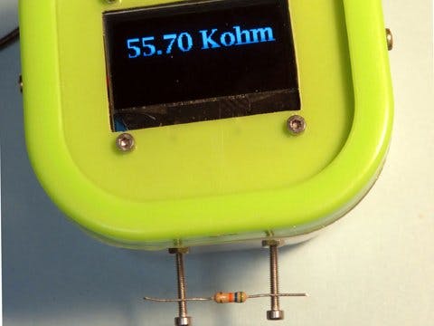
sprintf(_buffer, "%1u.%03u Kohm", (uint16_t)(value / 1000), (uint16_t)value % 1000);
else if (value < 100000.0)
sprintf(_buffer, "%02u.%02u Kohm", (uint16_t)(value / 1000), (uint16_t)(value / 10) % 100);
else if (value < 1000000.0)
sprintf(_buffer, "%03u.%1u Kohm", (uint16_t)(value / 1000), (uint16_t)(value / 100) % 10);
else
sprintf(_buffer, "%1u.%03u Mohm", (uint16_t)(value / 1000000), (uint16_t)(value / 1000) % 1000);
}
else
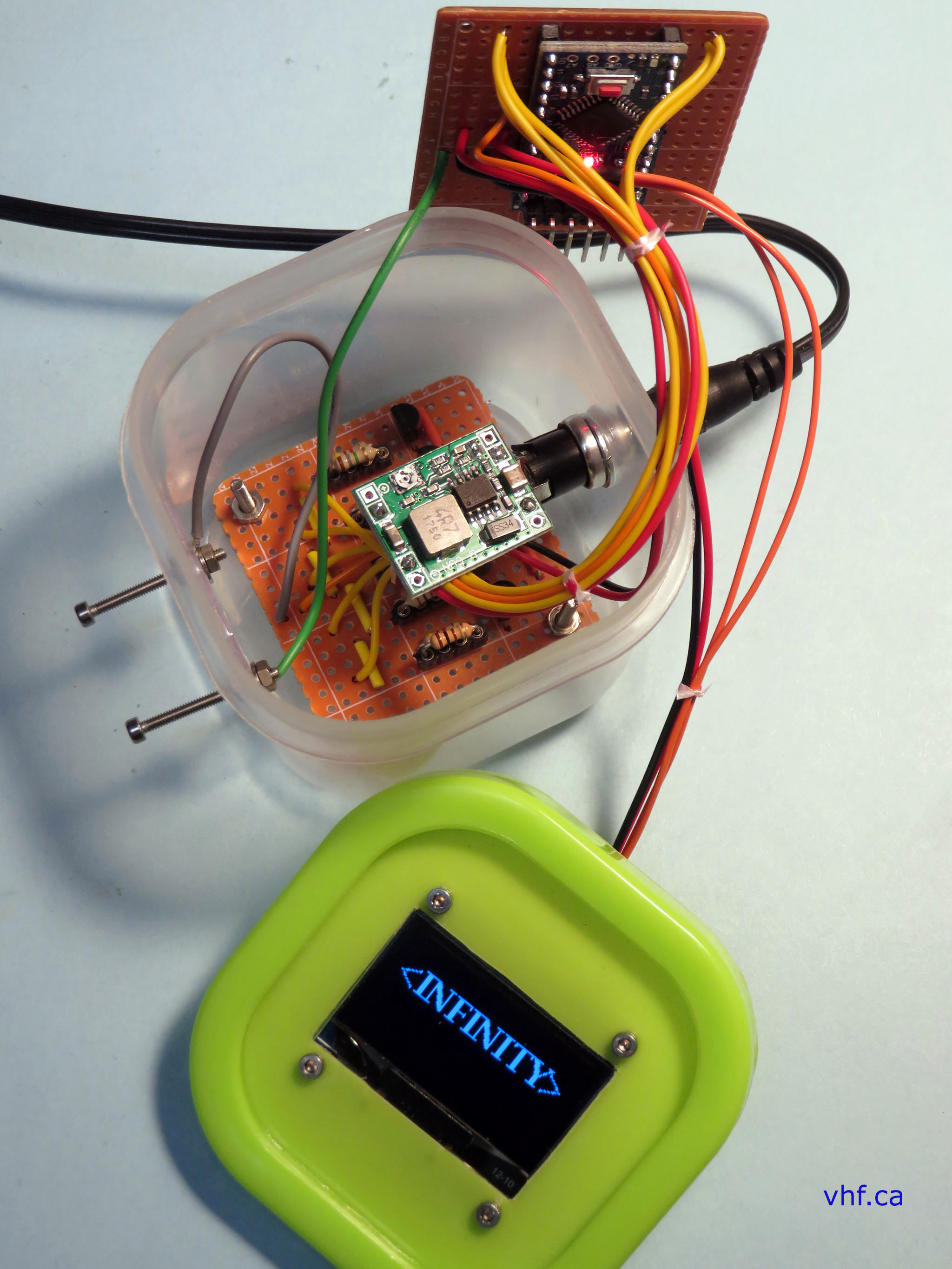
sprintf(_buffer, "<INFINITY>"); // Measuring probes open circuit
u8g2.setFont(u8g2_font_lubB14_tf); // Set Lucida 14 font
u8g2.clearBuffer();
u8g2.setCursor(5, 30);
u8g2.print(_buffer);
u8g2.sendBuffer();
// Serial.println(_buffer);
// Serial.println();
delay(1000); // update readings once per second. Default was 500
}
void ch_select(byte n) {
switch (n) {
case 0:
digitalWrite(CH0, LOW);
digitalWrite(CH1, HIGH);
digitalWrite(CH2, HIGH);
digitalWrite(CH3, HIGH);
digitalWrite(CH4, HIGH);
break;
case 1:
digitalWrite(CH0, HIGH);
digitalWrite(CH1, LOW);
digitalWrite(CH2, HIGH);
digitalWrite(CH3, HIGH);
digitalWrite(CH4, HIGH);
break;
case 2:
digitalWrite(CH0, HIGH);
digitalWrite(CH1, HIGH);
digitalWrite(CH2, LOW);
digitalWrite(CH3, HIGH);
digitalWrite(CH4, HIGH);
break;
case 3:
digitalWrite(CH0, HIGH);
digitalWrite(CH1, HIGH);
digitalWrite(CH2, HIGH);
digitalWrite(CH3, LOW);
digitalWrite(CH4, HIGH);
break;
case 4:
digitalWrite(CH0, HIGH);
digitalWrite(CH1, HIGH);
digitalWrite(CH2, HIGH);
digitalWrite(CH3, HIGH);
digitalWrite(CH4, LOW);
}
res = res_table[n];
} // end of code.


_3u05Tpwasz.png?auto=compress%2Cformat&w=40&h=40&fit=fillmax&bg=fff&dpr=2)
Comments