


Hardware components | ||||||
| × | 1 | ||||
| × | 1 | ||||
Software apps and online services | ||||||
| ||||||
 |
| |||||
Hand tools and fabrication machines | ||||||
 |
| |||||
Greetings everyone and welcome back. Time for something truly unique, meet Serpentime, a hybrid between a digital clock and a retro Snake game console, housed in an enclosure styled like a television set from the 1980s.
Serpentime is a compact, dual-mode creation that blends the utility of a digital clock with the charm of a retro Snake game console. With a single button press, it shifts from timekeeper to game machine, powered by an Xbox controller for a surprisingly immersive experience.
In clock mode, it fetches time, date, and weekday data via NTP and displays it in crisp white panels with bold black cut-out text.
Switch to game mode, and you’re greeted by a smooth Snake game driven by the controller’s left joystick, complete with gradient snake segments, pulsing food, and a live score overlay.
At its core is the ESP32-C6 Devkit, paired with an ILI9341 240×320 TFT display. For power, I built a custom circuit around the IP5306 power management IC, which steps up a 3.7V LiPo cell to a stable 5V which is enough to keep both the ESP and display running reliably.
The game logic is handled through a dedicated ESP32 library called BLEGamepadClient, which makes the Xbox controller pairing seamless. A buzzer adds tactile feedback when food is picked up, and a mode-switch button toggles between clock and game modes.
To bring the whole build to life, I designed an enclosure inspired by vintage 1980s television sets. The ILI9341 acts as the screen, framed by a retro shell complete with a dummy antenna and a 10-degree inclined base, a nod to old-school CRTs.
Materials RequiredThese were the materials we used in this project:
- ESP32-C6 Devkit V1
- ILI9341 Display
- Custom PCB (Provided by NextPCB)
- Buzzer
- Push Button
- Button PCB (Reuse from old Project)
- Connecting wires
- Breadboard
- XBOX Controller
- IP5306
- 10uF 1206 Capacitors
- 10K Resistor 0805
- Type C Port
- Vertical Push Button
- M2 screws
- Blue LED 0805
- 2R Resistor 1206
- 3.7V 600mAh LiPo Cell
- 3D printed parts
The idea to use an Xbox controller came from a project I had prepared earlier, where I demonstrated how to pair an ESP32 with the controller to perform various tasks. Initially, I used it to display button inputs on an ILI9341 screen.
https://www.hackster.io/Arnov_Sharma_makes/xbox-controller-with-esp32-389cfd
Once that concept was solid, I decided to repurpose the controller to drive one of my existing Snake game builds. I integrated BLE logic and input handling into the console code, and the result was a fully playable Snake game controlled via the Xbox controller’s left joystick.
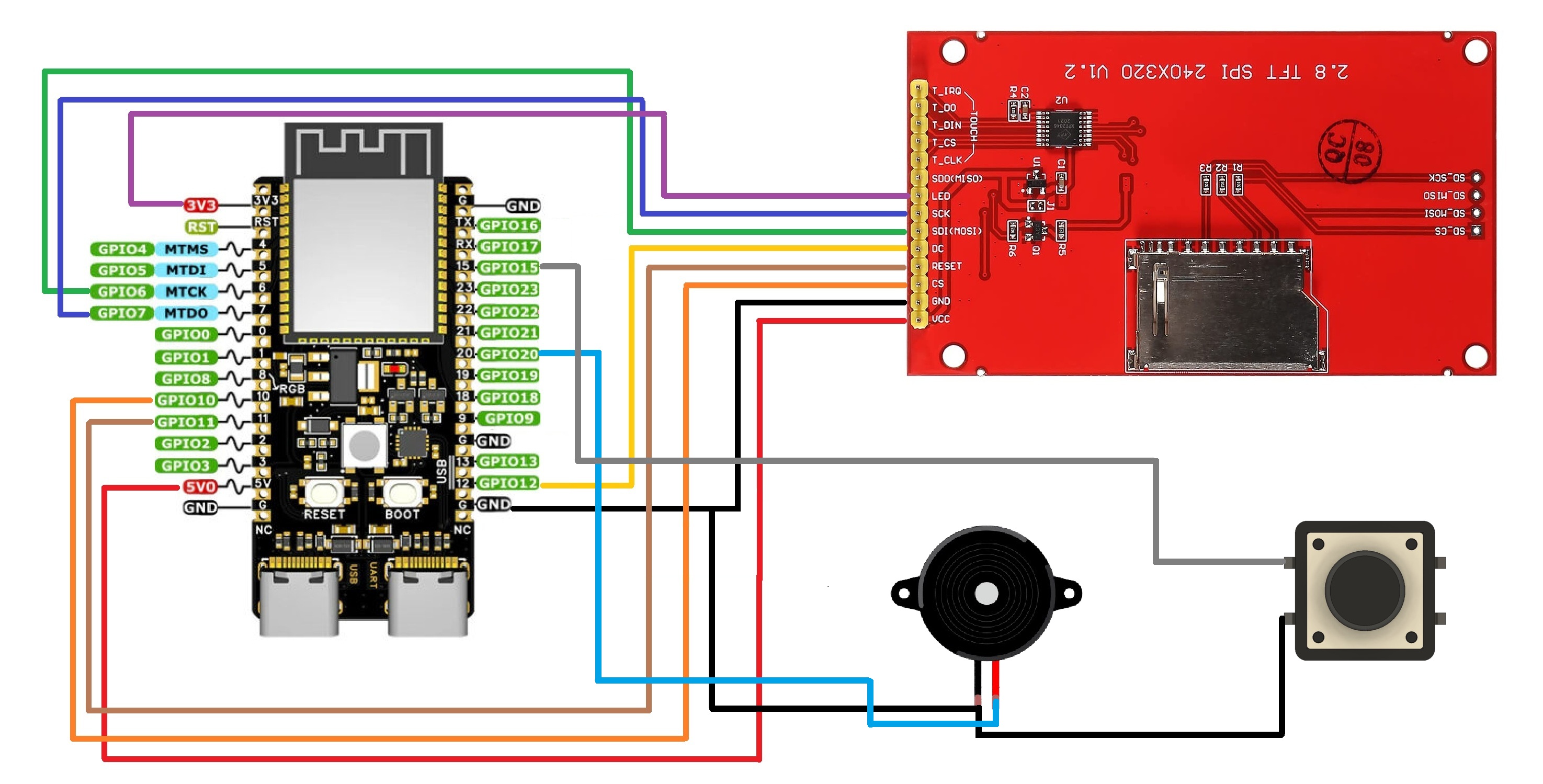
For wiring, I followed a simple diagram that connects the ILI9341 display to the ESP32-C6 via SPI, along with a few additional GPIOs. The setup includes connections for a mode-switch button and a buzzer, making the entire circuit compact and easy to replicate.
CODEHere's the code we used in this project and it's a simple one, we prepared this by using our previously created Internet Clock code and combining it with our previously made snake game console project code, this code we are using is a culmination of both projects combined into one.
#include <Arduino.h>
#include <WiFi.h>
#include <Adafruit_GFX.h>
#include <Adafruit_ILI9341.h>
#include <SPI.h>
#include <BLEGamepadClient.h>
#include <time.h>
// ------------------- Hardware -------------------
#define TFT_CS 10
#define TFT_DC 12
#define TFT_RST 11
#define TFT_MOSI 6
#define TFT_SCLK 7
#define BUZZER_PIN 20
#define MODE_BUTTON 15
#define LCD_WIDTH 320
#define LCD_HEIGHT 240
#define CELL_SIZE 8
#define GRID_WIDTH  (LCD_WIDTH / CELL_SIZE)
#define GRID_HEIGHT (LCD_HEIGHT / CELL_SIZE)
// ------------------- WiFi -------------------
const char *ssid = "YOUR SSID";
const char *password = "ADD PASS";
// ------------------- Display / Controller -------------------
Adafruit_ILI9341 gfx = Adafruit_ILI9341(TFT_CS, TFT_DC, TFT_RST);
XboxController controller;
XboxControlsEvent e;
// ------------------- Snake Game State -------------------
struct SnakeSegment { int x; int y; };
SnakeSegment snake[200];
int snakeLength = 5;
int dx = 1, dy = 0;
int foodX = 0, foodY = 0;
uint16_t foodColor = ILI9341_RED;
int prevTailX = 0, prevTailY = 0;
// ------------------- Mode Control -------------------
enum Mode { MODE_CLOCK, MODE_GAME };
Mode currentMode = MODE_CLOCK;
unsigned long lastButtonPress = 0;
// ------------------- Clock Panel geometry -------------------
const int PANEL_MARGIN = 10;
const int PANEL_W = LCD_WIDTH - 2 * PANEL_MARGIN;
const int PANEL_H_WEEK  = 40;
const int PANEL_H_DATE  = 44;
const int PANEL_H_TIME  = 66;
const int PANEL_Y_WEEK  = 36;
const int PANEL_Y_DATE  = PANEL_Y_WEEK + PANEL_H_WEEK + 8;
const int PANEL_Y_TIME  = PANEL_Y_DATE + PANEL_H_DATE + 8;
// ------------------- Clock cache -------------------
String lastWeekday = "";
String lastDate    = "";
String lastTime    = "";
// ------------------- Utilities -------------------
void drawBorderedCentered(const String &text, int y, int size,
uint16_t mainColor, uint16_t outlineColor) {
gfx.setTextWrap(false);
gfx.setTextSize(size);
int16_t x1, y1; uint16_t w, h;
gfx.getTextBounds(text, 0, 0, &x1, &y1, &w, &h);
int cx = (LCD_WIDTH - w) / 2;
gfx.setTextColor(outlineColor);
gfx.setCursor(cx - 1, y); gfx.print(text);
gfx.setCursor(cx + 1, y); gfx.print(text);
gfx.setCursor(cx, y - 1); gfx.print(text);
gfx.setCursor(cx, y + 1); gfx.print(text);
gfx.setTextColor(mainColor);
gfx.setCursor(cx, y); gfx.print(text);
}
bool isOnSnake(int x, int y) {
for (int i = 0; i < snakeLength; i++) {
if (snake[i].x == x && snake[i].y == y) return true;
}
return false;
}
// ------------------- Snake Game -------------------
void placeFood() {
for (int tries = 0; tries < 2000; tries++) {
int fx = random(0, GRID_WIDTH);
int fy = random(0, GRID_HEIGHT);
if (!isOnSnake(fx, fy)) { foodX = fx; foodY = fy; return; }
}
foodX = GRID_WIDTH/3; foodY = GRID_HEIGHT/3;
}
bool checkSelfCollision() {
for (int i = 1; i < snakeLength; i++) {
if (snake[0].x == snake[i].x && snake[0].y == snake[i].y) return true;
}
return false;
}
void beepFood() { tone(BUZZER_PIN, 1200, 100); }
void resetGame() {
gfx.fillScreen(ILI9341_BLACK);
dx = 1; dy = 0;
snakeLength = 5;
int cx = GRID_WIDTH / 2, cy = GRID_HEIGHT / 2;
for (int i = 0; i < snakeLength; i++) {
snake[i].x = cx - i; snake[i].y = cy;
}
placeFood();
}
void runSnakeGame() {
controller.read(e);
const float threshold = 0.5;
if (fabs(e.leftStickX) > fabs(e.leftStickY)) {
if (e.leftStickX > threshold && dx == 0)      { dx = 1;  dy = 0; }
else if (e.leftStickX < -threshold && dx == 0){ dx = -1; dy = 0; }
} else {
if (e.leftStickY > threshold && dy == 0)      { dx = 0;  dy = -1; }
else if (e.leftStickY < -threshold && dy == 0){ dx = 0;  dy = 1;  }
}
prevTailX = snake[snakeLength - 1].x;
prevTailY = snake[snakeLength - 1].y;
for (int i = snakeLength - 1; i > 0; i--) snake[i] = snake[i - 1];
snake[0].x += dx; snake[0].y += dy;
if (snake[0].x >= GRID_WIDTH) snake[0].x = 0;
if (snake[0].x < 0)           snake[0].x = GRID_WIDTH - 1;
if (snake[0].y >= GRID_HEIGHT) snake[0].y = 0;
if (snake[0].y < 0)           snake[0].y = GRID_HEIGHT - 1;
if (checkSelfCollision()) { resetGame(); return; }
gfx.fillRect(prevTailX * CELL_SIZE, prevTailY * CELL_SIZE,
CELL_SIZE, CELL_SIZE, ILI9341_BLACK);
for (int i = 0; i < snakeLength; i++) {
uint8_t b = map(i, 0, snakeLength, 255, 90);
uint16_t col = gfx.color565(b, 255 - b / 3, b / 5);
gfx.fillRoundRect(snake[i].x * CELL_SIZE, snake[i].y * CELL_SIZE,
CELL_SIZE, CELL_SIZE, 2, col);
}
int pulse = (millis() / 120) % 3;
int size = CELL_SIZE - 3 + pulse;
int offset = (CELL_SIZE - size) / 2;
gfx.fillRoundRect(foodX * CELL_SIZE + offset, foodY * CELL_SIZE + offset,
size, size, 2, foodColor);
if (snake[0].x == foodX && snake[0].y == foodY) {
if (snakeLength < (int)(sizeof(snake)/sizeof(snake[0]))) snakeLength++;
placeFood(); beepFood();
}
gfx.fillRect(0, 0, LCD_WIDTH, 16, ILI9341_BLACK);
gfx.setTextSize(2);
gfx.setTextColor(ILI9341_YELLOW);
gfx.setCursor(4, 2);
gfx.print("Score: ");
gfx.print(snakeLength - 5);
delay(120);
}
// ------------------- Clock -------------------
void drawStaticPanels() {
gfx.fillScreen(ILI9341_BLACK);
gfx.fillRect(PANEL_MARGIN, PANEL_Y_WEEK, PANEL_W, PANEL_H_WEEK, ILI9341_WHITE);
gfx.drawRect(PANEL_MARGIN, PANEL_Y_WEEK, PANEL_W, PANEL_H_WEEK, ILI9341_BLACK);
gfx.fillRect(PANEL_MARGIN, PANEL_Y_DATE, PANEL_W, PANEL_H_DATE, ILI9341_WHITE);
gfx.drawRect(PANEL_MARGIN, PANEL_Y_DATE, PANEL_W, PANEL_H_DATE, ILI9341_BLACK);
gfx.fillRect(PANEL_MARGIN, PANEL_Y_TIME, PANEL_W, PANEL_H_TIME, ILI9341_WHITE);
gfx.drawRect(PANEL_MARGIN, PANEL_Y_TIME, PANEL_W, PANEL_H_TIME, ILI9341_BLACK);
}
void updatePanelText(int y, int h, String &lastText,
const String &newText, int textSize) {
if (lastText != newText) {
// Erase old text area
gfx.fillRect(PANEL_MARGIN+2, y+2, PANEL_W-4, h-4, ILI9341_WHITE);
drawBorderedCentered(newText, y + (h/2 - 8),
textSize, ILI9341_BLACK, ILI9341_WHITE);
lastText = newText;
}
}
void runClock() {
struct tm timeinfo;
if (!getLocalTime(&timeinfo)) {
// Show error only inside time panel
gfx.fillRect(PANEL_MARGIN+2, PANEL_Y_TIME+2, PANEL_W-4, PANEL_H_TIME-4, ILI9341_WHITE);
drawBorderedCentered("Time Error", PANEL_Y_TIME + (PANEL_H_TIME/2 - 8),
3, ILI9341_BLACK, ILI9341_WHITE);
delay(500);
return;
}
char buf[20];
// Weekday
strftime(buf, sizeof(buf), "%A", &timeinfo);
updatePanelText(PANEL_Y_WEEK, PANEL_H_WEEK, lastWeekday, String(buf), 3);
// Date
strftime(buf, sizeof(buf), "%Y-%m-%d", &timeinfo);
updatePanelText(PANEL_Y_DATE, PANEL_H_DATE, lastDate, String(buf), 3);
// Time
strftime(buf, sizeof(buf), "%H:%M:%S", &timeinfo);
updatePanelText(PANEL_Y_TIME, PANEL_H_TIME, lastTime, String(buf), 4);
delay(200); // smooth refresh, no flicker
}
// ------------------- Setup -------------------
void setup() {
Serial.begin(115200);
pinMode(MODE_BUTTON, INPUT_PULLUP);
SPI.begin(TFT_SCLK, -1, TFT_MOSI, TFT_CS);
gfx.begin();
gfx.setRotation(1);
pinMode(BUZZER_PIN, OUTPUT);
WiFi.begin(ssid, password);
while (WiFi.status() != WL_CONNECTED) { delay(300); }
// Configure NTP with IST offset (UTC+5:30 = 19800 seconds)
configTime(19800, 0, "pool.ntp.org", "time.nist.gov");
controller.begin();
// Initial screen
drawStaticPanels();
runClock();
}
// ------------------- Loop -------------------
void loop() {
// Debounced button toggle
if (digitalRead(MODE_BUTTON) == LOW && millis() - lastButtonPress > 500) {
currentMode = (currentMode == MODE_GAME) ? MODE_CLOCK : MODE_GAME;
lastButtonPress = millis();
if (currentMode == MODE_GAME) {
gfx.fillScreen(ILI9341_BLACK);
resetGame();
} else {
drawStaticPanels();
lastWeekday = ""; lastDate = ""; lastTime = "";
runClock();
}
}
if (currentMode == MODE_GAME) {
runSnakeGame();
} else {
runClock();
}
}
CODE Breakdown.
#include <Arduino.h>
#include <WiFi.h>
#include <Adafruit_GFX.h>
#include <Adafruit_ILI9341.h>
#include <SPI.h>
#include <BLEGamepadClient.h>
#include <time.h>
We first includes the necessary libraries that handles Core Arduino functions WiFi connection Display rendering (GFX + ILI9341) SPI communication Xbox BLE controller input and the Time sync via NTP
#define TFT_CS 10
#define TFT_DC 12
#define TFT_RST 11
#define TFT_MOSI 6
#define TFT_SCLK 7
#define BUZZER_PIN 20
#define MODE_BUTTON 15
Next comes the Hardware Pins defination that defines pins for Linking GPIOs with TFT Display pins, Buzzer and the button.
#define LCD_WIDTH 320
#define LCD_HEIGHT 240
#define CELL_SIZE 8
#define GRID_WIDTH  (LCD_WIDTH / CELL_SIZE)
#define GRID_HEIGHT (LCD_HEIGHT / CELL_SIZE)
We next added Display and Grid Setup, in which we define screen resolution and grid size for the Snake game. Each cell is 8×8 pixels, creating a 40×30 grid.
const char *ssid = "YOUR SSID";
const char *password = "ADD PASS";
Here, we added Wifi Credentails, for using this sketch, you must add your WiFi credentials here to enable NTP Sync.
Adafruit_ILI9341 gfx = Adafruit_ILI9341(TFT_CS, TFT_DC, TFT_RST);
XboxController controller;
XboxControlsEvent e;
This section Initializes the TFT Display and Xbox BLE controller.
struct SnakeSegment { int x; int y; };
SnakeSegment snake[200];
int snakeLength = 5;
int dx = 1, dy = 0;
int foodX = 0, foodY = 0;
uint16_t foodColor = ILI9341_RED;
int prevTailX = 0, prevTailY = 0;
This is the State Section for the Snake game in which Snake is stored as an array of segments, the dx/dy controls the movement direction, foodX/Y tracks the food position and prevTailX/Y is used to erase the last segment.
enum Mode { MODE_CLOCK, MODE_GAME };
Mode currentMode = MODE_CLOCK;
unsigned long lastButtonPress = 0;
Here is the Mode Switching section that tracks the current mode and the button toggle between clock and game with debounce logic.
const int PANEL_MARGIN = 10;
const int PANEL_W = LCD_WIDTH - 2 * PANEL_MARGIN;
const int PANEL_H_WEEK  = 40;
const int PANEL_H_DATE  = 44;
const int PANEL_H_TIME  = 66;
const int PANEL_Y_WEEK  = 36;
const int PANEL_Y_DATE  = PANEL_Y_WEEK + PANEL_H_WEEK + 8;
const int PANEL_Y_TIME  = PANEL_Y_DATE + PANEL_H_DATE + 8;
Using this section, the layout for weekday, date and time panels is defined.
String lastWeekday = "";
String lastDate    = "";
String lastTime    = "";
This section stores previously displayed text to avoid flickering redraws.
void drawBorderedCentered(const String &text, int y, int size,
uint16_t mainColor, uint16_t outlineColor) {
  gfx.setTextWrap(false);
  gfx.setTextSize(size);
  int16_t x1, y1; uint16_t w, h;
  gfx.getTextBounds(text, 0, 0, &x1, &y1, &w, &h);
  int cx = (LCD_WIDTH - w) / 2;
  gfx.setTextColor(outlineColor);
  gfx.setCursor(cx - 1, y); gfx.print(text);
  gfx.setCursor(cx + 1, y); gfx.print(text);
  gfx.setCursor(cx, y - 1); gfx.print(text);
  gfx.setCursor(cx, y + 1); gfx.print(text);
  gfx.setTextColor(mainColor);
  gfx.setCursor(cx, y); gfx.print(text);
}
This section draws text with a 1-pixel outline for contrast and centers it horizontally at position y.
bool isOnSnake(int x, int y) {
  for (int i = 0; i < snakeLength; i++) {
    if (snake[i].x == x && snake[i].y == y) return true;
  }
  return false;
}
This section checks if a grid cell is occupied by the snake, preventing food from spawning on cells occupied by the snake.
void placeFood() {
  for (int tries = 0; tries < 2000; tries++) {
    int fx = random(0, GRID_WIDTH);
    int fy = random(0, GRID_HEIGHT);
    if (!isOnSnake(fx, fy)) {
      foodX = fx;
      foodY = fy;
      return;
    }
  }
  foodX = GRID_WIDTH/3;
  foodY = GRID_HEIGHT/3;
}
This function places food randomly, avoiding the snake.
bool checkSelfCollision() {
  for (int i = 1; i < snakeLength; i++) {
    if (snake[0].x == snake[i].x && snake[0].y == snake[i].y) return true;
  }
  return false;
}
Another important function which checks if the head overlaps with any body segment.
void beepFood() {
  tone(BUZZER_PIN, 1200, 100);
}
This function plays a short beep on the buzzer when food is eaten.
void resetGame() {
  gfx.fillScreen(ILI9341_BLACK);
  dx = 1; dy = 0;
  snakeLength = 5;
  int cx = GRID_WIDTH / 2, cy = GRID_HEIGHT / 2;
  for (int i = 0; i < snakeLength; i++) {
    snake[i].x = cx - i;
    snake[i].y = cy;
  }
  placeFood();
}
This part resets snake position and direction, then places food after the reset.
void runSnakeGame() {
  controller.read(e);
This Function reads the current state of the Xbox BLE controller and stores it in e. This includes joystick positions and button states.
const float threshold = 0.5;
  if (fabs(e.leftStickX) > fabs(e.leftStickY)) {
    if (e.leftStickX > threshold && dx == 0)      { dx = 1;  dy = 0; }
    else if (e.leftStickX < -threshold && dx == 0){ dx = -1; dy = 0; }
  } else {
    if (e.leftStickY > threshold && dy == 0)      { dx = 0;  dy = -1; }
    else if (e.leftStickY < -threshold && dy == 0){ dx = 0;  dy = 1;  }
  }
We next have direction controls in which we use the left joystick to control snake direction. It also prevents reversing into itself by checking dx==0 or dy==0 and filters out small joystick noise, which is important because mine has a little problem of Drift.
prevTailX = snake[snakeLength - 1].x;
  prevTailY = snake[snakeLength - 1].y;
  for (int i = snakeLength - 1; i > 0; i--) snake[i] = snake[i - 1];
  snake[0].x += dx;
  snake[0].y += dy;
This Section moves the snake forward, which it does by saving the tail position to erase later and then shifting all segments forward and moving the head in the current direction.
if (snake[0].x >= GRID_WIDTH)  snake[0].x = 0;
  if (snake[0].x < 0)            snake[0].x = GRID_WIDTH - 1;
  if (snake[0].y >= GRID_HEIGHT) snake[0].y = 0;
  if (snake[0].y < 0)            snake[0].y = GRID_HEIGHT - 1;
This Section make sures that if the snake goes off-screen, it wraps around to the opposite edge.
if (checkSelfCollision()) {
    resetGame();
    return;
  }
If Snake bites itself, the game resets.
for (int i = 0; i < snakeLength; i++) {
    uint8_t b = map(i, 0, snakeLength, 255, 90);
    uint16_t col = gfx.color565(b, 255 - b / 3, b / 5);
    gfx.fillRoundRect(snake[i].x * CELL_SIZE, snake[i].y * CELL_SIZE,
                      CELL_SIZE, CELL_SIZE, 2, col);
  }
Using this section, we Draw each snake segment with a gradient color by using fillRoundRect() for smooth rounded visuals.
if (snake[0].x == foodX && snake[0].y == foodY) {
    if (snakeLength < (int)(sizeof(snake)/sizeof(snake[0]))) snakeLength++;
    placeFood();
    beepFood();
  }
If the head touches the food, this Increases snake length (up to 200 max) and places new food along with a follow-up beep.
gfx.fillRect(0, 0, LCD_WIDTH, 16, ILI9341_BLACK);
  gfx.setTextSize(2);
  gfx.setTextColor(ILI9341_YELLOW);
  gfx.setCursor(4, 2);
  gfx.print("Score: ");
  gfx.print(snakeLength - 5);
This section manages the scoreboard, clears the top bar, and displays the current score based on the segment added.
delay(120);
}
This part adds a short delay to control game speed.
Once everything was working flawlessly on the breadboard and the code had been thoroughly tested, I moved on to the next phase: device design.
Device DesignNow onto the device design my goal was to create a clock that truly stands out. While browsing Pinterest, I came across a post featuring a vintage-style TV rendered in a modern art aesthetic. That concept stuck with me, and I decided to build a clock housed inside a retro TV-inspired enclosure. The ILI9341 display was a perfect fit for the screen, and to enhance the look, we added a top-mounted antenna that also serves as a structural connector between the front and back halves of the body.
I began with rough sketches to finalize the shape, then took photo of the sketch and imported it into Fusion 360 as a canvas. Using manual tracing, I modeled the TV body, scaling it slightly larger than the ILI9341 to ensure a snug fit. The enclosure was split into two halves and shelled out. The front section holds the display, which sits behind a chamfered face mimicking the thick bezels and angled edges of old television sets.
We reused two components from previous builds: the power circuit from our Portable Studio Light project and a button board from the Gameboy XL project. Their 3D models were imported and positioned in the rear half of the enclosure. We added a slot on the left side for the USB Type-C port and the power switch. A LiPo cell was also modeled and placed beneath the circuit. The board is secured with a single M2 screw mounted at the center, resting on a screw boss and supported by ribs near the USB area.
To enable external control, we designed a switch actuator on the back. It sits above the button board and, when pressed, pushes down on the tactile switch to register input.
To join the front and back sections, we used two structural elements: the antenna on top and a base stand at the bottom. Both are positioned along the parting line and screwed into place, locking the enclosure together.
The antenna rests on a circular hub that connects both halves, while the base stand features four legs angled to tilt the entire clock forward by 10 degrees giving it a classic, display-ready posture.
Thanks to these design choices, the final clock has a distinctly vintage character that reflects our creative effort.
After completed the Design, we exported the Mesh files and 3D printed both Front and Back Sections in white PLA, Stand and Top holder were both printed in Brown PLA and antenna was printed in Black PLA. For inside, we have modeled a part that holds down ILI9341 display in place, this part was also printed in Brown PLA.
PCB DesignFor this build, we’re repurposing a circuit originally designed for a portable studio light project. That setup featured an ESP12F module connected to WS2812B LEDs, all powered by an IP5306 power management IC. While we’re reusing the same board, we won’t be using the ESP12F, the LED array, or the onboard AMS1117 regulator; only the IP5306 section will be active.
The IP5306, a compact SOIC-8 package, has been a reliable choice in many of our battery-powered projects. It efficiently boosts a 3.7V Li-ion or LiPo cell to a stable 5V at up to 2.4A, and includes essential features like overcharge protection, undervoltage cutoff, battery level monitoring, and charging status indication
Below is its datasheet if you want more info on this IC.
https://www.skytech.ir/DownLoad/File/2566_IP5306.pdf
For charging, there is a Type C port and for turning the setup ON or OFF, there is a vertical type C port both mounted side by side.
NextPCB PCB ServiceAfter completing the PCB Design, Gerber Data was sent to HQ NextPCB, and an order was placed in a Green solder mask with White silkscreen.
After placing the order, the PCBs were received within a week, and the PCB quality was pretty great.
In addition, I have to bring in HQDFM to you, which helped me a lot through many projects. Huaqiu’s in-house engineers developed the free Design for Manufacturing software, HQDFM, revolutionizing how PCB designers visualize and verify their designs.
Take advantage of NextPCB's Accelerator campaign and get 2 free assembled RP2040-based PCBs for your innovative projects.
https://www.nextpcb.com/blog/rp2040-free-pcba-prototypes-nextpcb-accelerator
This offer covers all costs, including logistics, making it easier and more affordable to bring your ideas to life. SMT services can be expensive, but NextPCB is here to help you overcome that hurdle. Simply share your relevant project, and they'll take care of the rest. Don't miss out on this amazing opportunity to advance your tech creations!
HQDFM: Free Online Gerber Viewer and DFM Analysis ToolAlso, NextPCB has its own Gerber Viewer and DFM analysis software.
Your designs are improved by their HQDFM software (DFM) services. Since I find it annoying to have to wait around for DFM reports from manufacturers, HQDFM is the most efficient method for performing a pre-event self-check.
This is what I see in the online Gerber Viewer. It's decent for a quick look, but not entirely clear. For full functionality—like detailed DFM analysis for PCBA—you’ll need to download the desktop software. The web version only offers a basic DFM report.
With comprehensive Design for Manufacture (DFM) analysis features, HQDFM is a free, sophisticated online PCB Gerber file viewer.
With over 15 years of industry experience, it offers valuable insights into advanced manufacturing processes. If you’re looking for reliable PCB services at a budget-friendly price, HQ NextPCB is definitely worth checking out.
PCB Assembly- The PCB assembly process begins by applying solder paste to each SMD component pad one at a time with a solder paste dispensing needle; we are using 63/37 Sn/Pb solder paste here.
- Next, we use an ESD tweezer to pick and arrange all SMD components on the top side of the board.
- We pick the circuit and place it on the Reflow hotplate, which heats the PCB to the solder paste melting temperature, causing all SMD components to permanently solder to their pads.
- Now come the through-hole components; we begin by installing the Push Switch, followed by the type C Port. Board is then filpped over and we solder both through-hole component pads using a soldering iron.
For power, we’re using a 3.7V 600mAh LiPo cell. Its positive and negative terminals are soldered directly to the battery connector on the power circuit. The system is activated by pressing a vertical push button, which powers up the board and lights up the indicator LED that confirms the setup is operational.
To verify, we measure the output voltage across the board, which reads a stable 5V.
Charging is straightforward: just connect a USB Type-C cable using any standard smartphone charger. During charging, the indicator LED blinks to show activity, and once the battery is fully charged, the LED remains solid to indicate completion.
WIRINGWe now start the wiring process which begins by connecting the TFT Display with ESP32 C6 Dev kit in the following order.
- DISPLAY's MOSI to GPIO6
- SCK to GPIO7
- Chip Select to GPIO10
- Reset to GPIO11
- DC to GPIO12
- The LED Pin of Display goes to 3.3V of the DevKit.
- VCC goes to 5V
- GND to GND
We’ve reused a button PCB from a previous project it features a 6×6 push button mounted on a small board that fits neatly into our enclosure. The button’s signal pin is connected to GPIO15 on the ESP32-C6, while the other terminal is tied to ground.
Additionally, we’ve integrated a buzzer with the ESP32-C6 dev kit. The buzzer’s positive lead is wired to GPIO20, and its negative lead is connected to ground.
To complete the power setup, we’ve connected the output of our IP5306-based power circuit directly to the ESP32-C6 dev kit: 5V goes to the dev kit’s 5V input, and ground is shared between both boards finalizing the entire wiring process
Front Enclosure—Screen Assembly- The front enclosure assembly begins with positioning the ILI9341 display into its designated mounting slot.
- Once aligned, we secure it using a holding plate, which is fastened with four M2 screws. This plate ensures the display remains firmly in place and properly seated within the enclosure.
The back enclosure assembly begins with inserting the switch actuator into its designated slot. Once in place, the button PCB is positioned directly above it and secured using two M2 screws, ensuring the actuator can reliably press the onboard push button when triggered.
Next, the LiPo cell is carefully placed into its allocated compartment. The power circuit is then aligned over its central mounting boss and fastened with a single M2 screw. This not only secures the board but also holds the LiPo cell firmly in position beneath it, completing the internal layout of the rear section.
Final Assembly- Assembly starts by placing the buzzer in its designated spot. Next, the ESP32-C6 Devkit is mounted onto the screen holder, and the front and back sections of the enclosure are closed together.
- The antenna holder is then positioned on top, aligned with the parting line, and secured using two M2 screws, locking all three sections firmly in place.
- From the bottom, the stand is attached and fastened with four M2 screws. Like the antenna holder, the stand also reinforces the connection between the front and back halves.
- Finally, the antenna is mounted onto the holder and secured with a single M2 screw. With that, the full assembly is complete.
End Result of this build is a fully functional hybrid that doubles as a desk clock and a Snake game console. It fetches real-time data over WiFi and seamlessly switches into game mode, controlled via an Xbox controller paired over BLE. The ESP32-C6 handles everything smoothly, delivering reliable performance throughout.
Powered by a 3.7V 600mAh LiPo cell, the setup offers a solid 6–7 hours of backup, which is reasonable given the power demands of the ILI9341 display. For future iterations, switching to an E Ink display could drastically cut power consumption and extend battery life which is a promising upgrade for long-term use.
Clock and GamingBy pressing the Back switch, the desk clock seamlessly transforms into a Snake game console. Once the Xbox controller is powered on, it automatically pairs with the ESP32-C6 via Bluetooth Low Energy (BLE), allowing instant gameplay using the left joystick.
As the snake consumes each food dot, the score counter increases and the snake grows progressively longer. If the player accidentally collides with the snake’s own body, the game ends and the score resets, just like the classic rules.
When you're done playing, a simple press of the same switch reverts the setup back to its original clock mode, making the transition between timekeeping and gaming smooth and intuitive.
Special thanks to HQ NextPCB for providing components that I've used in this project; check them out for getting all sorts of PCB or PCBA-related services for less cost.
Thanks for reaching this far, and I will be back with a new project soon.

_t9PF3orMPd.png?auto=compress%2Cformat&w=40&h=40&fit=fillmax&bg=fff&dpr=2)


Comments