

Hardware components | ||||||
 |
| × | 1 | |||
 |
| × | 1 | |||
Software apps and online services | ||||||
| ||||||
 |
| |||||
Hand tools and fabrication machines | ||||||
 |
| |||||
Greetings everyone, and welcome back.
Here’s something comically huge: meet the Motorola DynaTAC MAX, my take on the OG Motorola DynaTAC 8000X, but with a twist.
The twist here is the sheer scale of the project. I modeled a comically large replica of the Motorola DynaTAC 8000X, 3D printed the body, and made a nearly matching replica that actually works.
For now, it works as a soundboard and a Bluetooth speaker.
The soundboard feature works as follows: I modeled buttons similar to the Motorola DynaTAC, and each button has its own push button connected to a Raspberry Pi Pico W and DFPlayer Mini setup. I added audio clips of numbers one to nine on an SD card. When any number button is pressed—say, one—the device plays the audio that says “one.” Similarly, it works for two, three, four, and so on.
Additionally, there are six extra buttons similar to the original DynaTAC buttons. These have unique audio clips assigned to each. Pressing the star button plays a screaming sound, the hashtag button plays a meme sound effect, one button plays the Halo theme song, another plays the “and his name is John Cena” meme, and I even added a Rickroll to the setup. It’s a perfect way to annoy your neighbours, as it gets super loud.
There’s also a full Bluetooth speaker module fitted inside the device. It includes knobs for controlling volume, treble, and bass of the Bluetooth speaker.
The idea behind this project was to make a giant replica of the Motorola DynaTAC, on which I will slowly add new features and eventually turn it into a fully functional phone. I also wanted to add a chatbot to this setup, but that will be covered in version 2 of the project.
This article covers the entire assembly process of the build, including the electronics assembly, sanding and priming process, code for the soundboard, Bluetooth speaker implementation, and more—so let’s get started with the build.
MATERIALS REQUIREDThese were the materials used in this project-
- Custom PCBs
- ZK1002 Bluetooth Module
- CD74HC4067 Multiplexer IC
- Raspberry Pi PICO W
- DF Mini Player
- SD card
- Push Button 12x12
- RGB LED WS2812B
- LM317 LDO DPAK Package
- 1uF Capacitor
- 10uF Capacitor
- 330 Ohms Resistor
- 1K Resistor
- 10k Resistor
- 0805 Indicator LED
- Female Header Pins
- Connecting Jumper wires (single core)
- Speaker 8 ohms 5W
- Speaker 4 Ohms 25W
- Speaker 4 Ohms 10W
- Battery 12V 5.2Ah with BMS
- M6 Nuts and Bolts set
- M2 Screws
- M4 Screws
- 3D printed Parts
- Automotive filler
- Sandpapers
- Spray paint
- Spray primer
- TTGO T display S3 Long Board
- 7 Rolls of Hyper PLA White Filament
- 1 Roll of Hyper PLA Black Filament
- 1 Roll of Hyper PLA Grey Filament
- 1 Roll of Hyper PLA RED Filament
- Patience and Time
Back in 1973, Martin Cooper, a Motorola engineer, made the first-ever handheld mobile phone, called the DynaTAC. The DynaTAC model boomed in the early 1980s. At that time, the phone was infamously called the “brick phone, ” and in 1983, the Motorola DynaTAC 8000X became the first commercially available handheld mobile phone.
The name “brick” comes from the fact that it was a 33 cm tall phone that weighed almost 800 grams, with a huge antenna. It had a battery life of about 30 minutes after nearly 10 hours of charging. The cost was also diabolical—around $4, 000 at that time, which was extremely expensive even in that economy. Because of the price tag, it was more of a status symbol.
It became a pop culture icon, appearing in many movies. It was used by serious business people and was a technology ahead of its time.
It basically laid the foundation for the handheld phone era, which eventually evolved into the smartphone.
3D MODEL BREAKDOWNThe whole project started with researching the phone, studying images from different perspectives and views to capture details that would later be used in the model.
We selected two clear images of front-view and side-view images, then imported them into Autodesk Fusion 360 using the import canvas option in Fusion.
Both images were calibrated so that the width of the phone measured around 240 mm, which scaled it correctly and allowed us to begin the modeling process.
From the front view, we sketched the outline of the phone and then extruded it, which gave us a solid block. This solid block was then viewed from the left side, where we created another sketch that followed the DynaTAC’s shape and performed an extrude cut on the body. This resulted in a similarly shaped body resembling the Motorola phone. We continued refining the shape to make it look exactly like the Motorola DynaTAC.
After achieving a proper body, we moved on to the next step, which was dividing the body into two parts: the front side and the back side. We then hollowed out both parts using the shell command. The idea was to create a box-like structure with a main body and a lid—the front acting as the lid and the back as the main body. On the front body, we started adding details like buttons, the screen, speaker grills, and all the elements present on the Motorola phone.
We also modeled an antenna that looks identical to the original one. This antenna is placed on the back body. Since it was too long, we split it into two parts that can be glued together.
For working switches, we designed a switch PCB that contains standard 12×12 mm push buttons. These switches are positioned beneath the main buttons of the phone, so when a button is pressed, the push switch underneath is activated and registers the input. The switch PCB is held in place using screw bosses and PCB holders.
We used the same switch PCB design for all buttons. Each PCB contains six buttons, and since we have a total of 18 buttons, we used three switch PCBs.
We also added a TTGO T-Display S3 long board in the area where the original phone had a seven-segment display. This replaces the old display with modern technology.
We included two different speaker systems in this project. For the soundboard, the front speaker is used, while for the Bluetooth speaker, four speakers are placed on the back body with speaker grills. The front speaker assembly consists of a grill part and a speaker holder, both screwed together and mounted from the inside of the front body.
In the lower section, the DynaTAC originally had nine buttons labeled RCL, CLR, SND, STO, FCN, END, PWR, LOCK, and VOL. Due to space constraints, we used only six of them. The lower buttons—PWR, LOCK, and VOL—were replaced with knobs designed for controlling the Bluetooth module.
We are using the ZK1002T Bluetooth Amplifier Module, which has three potentiometers for controlling volume, bass, and treble. For its placement, we made three holes aligned with the centers of the potentiometers. The idea is to pass the shafts through these holes and use nuts to tighten them in place, effectively securing the entire Bluetooth module. We also modeled custom potentiometer knobs, which will be 3D printed in a different color.
The buttons on the DynaTAC were white, with letters and numbers printed in black. We could have painted them, but I tend to overengineer, and since I have a great 3D printer, I used tolerances and clearances instead.
On each button, I added the numbers and performed an extrude cut, creating a 2 mm deep cavity. Inside this cavity, I modeled the numbers again, but with an offset outline. When extruded, this created a 0.2 mm gap.
This gap is key; we print the button in black PLA, then pressure-fit the letters or numbers into place. We used this method for all the number buttons, as well as the lower buttons labeled RCL, SND, etc.
Around the buttons, I also added an additional part that will be printed in black PLA. This acts as an aesthetic element, creating a dual-tone effect around the buttons. It wasn’t part of the original design, but it’s my custom addition.
The back body also houses a few major components: the main switch for turning the device on and off, a DC jack for charging the battery pack, and a lithium-ion battery pack.
Now comes the challenging part, the device is super huge, almost 1000 mm long. So how did I print it?
Simple: by dividing each part into smaller pieces that could be printed on my 3D printer, which has a build volume of 255 × 255 × 255 mm. I divided the front body into seven parts, each joined together using three M6 nuts and bolts.
Using nuts and bolts is crucial for maintaining joint strength, as superglue alone wouldn’t be sufficient.
Similarly, the back body was also divided, but into five larger parts.
The front and back body assemblies, with all parts joined together, are secured using M3 screws placed along the left and right sides of the model. This holds both the front and back parts firmly together.
FINAL DESIGNHere’s how the design finally turned out. I created renders in KeyShot, and they look mind-blowing NGL. The model creation was the easy part, but what comes next is much harder: converting this digital model into a truly physical one.
3D PRINTED PARTSFor printing the front and back body, we used white Hyper PLA for most parts. Roughly, we used almost six rolls just for the body. The front body was divided into seven different parts, which were printed separately, and the back body was divided into five parts, all printed in white.
The remaining parts, such as the buttons, were also printed using white Hyper PLA. The lower buttons were printed in grey PLA, except for one, which was printed in red Hyper PLA. Similarly, grey PLA was used to print the front speaker grill and holder. The letters, numbers, backside speaker grills, and antenna were all printed using black Hyper PLA.
SLICER SETTINGS HACKNow, here’s a neat little trick that everyone should know if they are printing big parts that require a lot of support material.
Usually, when we add supports, they can be quite hard to remove from the printed parts due to the default settings. The part prints well, but the supports are tricky to remove.
Here’s the solution: we just need to adjust the Z-distance setting from the default (around 0.1–0.15 mm) to about 0.3 mm. This works with both normal supports and tree supports.
What this Z-distance does is create a small gap between the part and the support, making the supports much easier to remove.
SPEAKERSFor the audio part of this project, we used three different types of speakers. The first is a 5W, 8Ω speaker, which is connected to the Pico Driver Board and acts as the output for the soundboard.
Next, for the Bluetooth audio system, we used two different types of speakers: a pair of rectangular 8Ω 15W speakers and a pair of 15W 4Ω square speakers salvaged from an old Samsung home theater.
In this setup, one 8Ω speaker is connected in series with one 4Ω speaker, and this pair is connected to the left channel of the Bluetooth module.
Similarly, the other speaker pair is connected to the right channel.
FRONT BODY ASSEMBLYWe begin the front body assembly by putting all the parts together.
- We printed a total of seven parts, and using M6 nuts and bolts, we joined each part, starting from the top to the bottom.
- We used two nuts and bolts for joining each pair of parts.
We could have used regular superglue or other adhesives, but they wouldn’t provide enough strength. Using nuts and bolts gives the assembly proper structural integrity.
FILLER PREP WORKFor filler material, we are using a 3M automotive two-part filler, which consists of a filler and a hardener.
By adding 2% hardener and mixing it thoroughly with filler, we get a compound that can be used to fill gaps, layer lines, and other imperfections on our printed body.
The filler process is an important step before painting. Applying filler to 3D prints, then sanding the surface smooth, followed by primer and paint, results in a finish so clean that it no longer looks 3D printed at all.
FRONT BODY FILLER PROCESS- Using a paint scraper, we take a small amount of the filler compound mix and apply it across the front body.
- We start by filling the gaps between the joined parts, then move on to areas where layer lines are visible.
The goal is to spread the filler over the 3D-printed surface, so it settles into the layer lines and gaps between parts.
SANDING PROCESS MATERIALS & PREP WORKThe next process after applying filler is sanding. But before starting, we need to prepare properly.
Here, we are primarily using two grits of sandpaper, 100 grit for coarse grinding and 150 grit for a medium finish.
To use sandpaper effectively, we use a sandpaper holder, which is a really useful tool for sanding. I cut the sandpaper into strips, attach them to the holder, and use it for sanding. It’s more effective and works better than using sandpaper alone.
Also, since we are sanding filler material that produces fine dust particles, we use a mask with proper filters. Here, I’m using a 3M mask that protects me well, and it looks cool too.
Gloves are also recommended, as this process can get quite messy.
FRONT BODY SANDING PROCESSNow comes the most fun part of the project for me, sanding.
I begin by sanding the top surfaces of the front body, followed by sanding down the gaps between parts that were filled with filler. The edges of the parts with fillets are also sanded.
The goal here is not to sand down the plastic itself, but the added filler. This way, we remove excess filler while keeping the plastic body intact.
Doing this removes the visible gaps between layer lines and evens out the surface.
BACK BODY ASSEMBLYThe back body assembly is carried out similarly to the front body. All five parts are aligned together and then joined using M6 nuts and bolts. Each joint requires three nuts and bolts.
Since the back body is thicker than the front body, two M6 nuts and bolts would be insufficient, so three are used for each joint.
BACK BODY FILLER PROCESSFor the filler process, we mix a new batch of filler compound and apply it to the gaps between the joined parts, as well as across the surface of the back body, especially in areas where we can see unevenness.
The goal here is to apply filler evenly across the entire surface.
BACK BODY SANDING PROCESSThe back body sanding process comes next, in which we sand down the entire surface just like we did with the front body.
The focus is on sanding the filler material to achieve a smooth finish that removes all visible layer lines, gaps, and unevenness from the print.
FRONT & BACK BODY PRIMER PROCESSNow comes the priming process, and this one was quite lengthy.
For painting, primer is a mandatory base coat because it helps the paint adhere better to the surface, improves durability, and highlights any remaining imperfections that need fixing.
Here, I used a spray primer, which works just like spray paint but is specifically designed as a base layer.
I started by applying light, even coats across the entire body, gradually covering the full surface. After the first coat, I let the primer dry for a couple of hours, then applied a second coat and allowed it to dry again.
Finally, I applied a third coat for a consistent and well-prepared surface.
MORE SANDING- FRONT & BACK BODYWe then use finer-grit sandpaper (150) and begin sanding both the front and back body. The goal here is to sand everything thoroughly, every surface, every face, every edge, and every corner.
This step is done to achieve an ultra-smooth surface, which is essential for painting. A smoother surface allows the paint to adhere evenly and results in a clean, professional finish without visible imperfections or texture.
PAINT PROCESSFinally, we begin the painting process, using cream white spray paint, specifically an aerosol paint can.
- We slowly and steadily coat both the front and back body with the first coat. The key here is to apply light, even layers across the entire surface.
- After letting the first coat dry, we apply a second coat and then leave the parts for about 3 hours to dry. After that, we proceed with the third coat.
By the third coat, we achieve a refined, properly painted surface that resembles aged white plastic with a slight beige-white theme.
PCB DESIGN- PICO DRIVERNow comes the electronics part of this project.
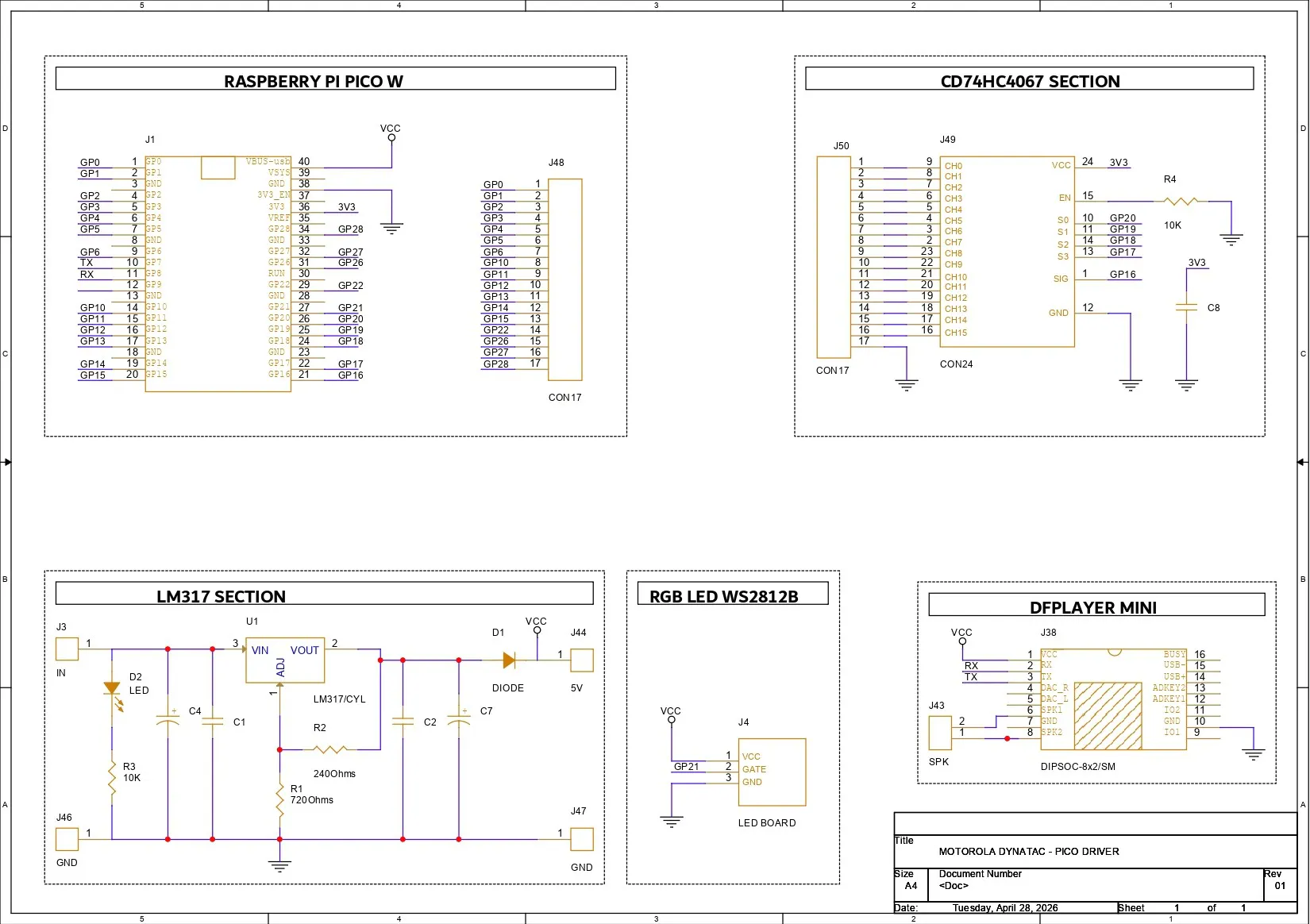
For this build, we designed two PCBs. The first one is the Pico Driver Board, consisting of a Raspberry Pi Pico W paired with a CD74HC4067 IC, which is a multiplexer. We also connected a DFPlayer Mini to the Pico W. For power, we added an LM317 LDO setup, which allows the device to be powered from a 12V source.
We used the CD74HC4067 multiplexer IC in our circuit, which allows multiple input signals to be read using only a few microcontroller pins. This IC acts like an electronic rotary switch: it connects one of sixteen input channels to a single output pin at a time, depending on the control signals provided.
The CD74HC4067 has 16 signal channels (C0–C15) and one common pin (SIG). Four select pins (S0–S3) determine which channel is currently connected to the common pin. By sending a binary value to these four select lines, the microcontroller can quickly choose which input channel to read. For example, when the select lines represent binary 0000, channel C0 is connected; when they represent 0001, channel C1 is connected, and so on up to C15.
GPIO16 of the Pico W is connected to the SIG pin of the multiplexer IC. GPIO20 is connected to S0, GPIO19 to S1, GPIO18 to S2, and GPIO17 to S3.
The GND of the multiplexer is connected to the GND of the Pico W, and the VCC of the multiplexer is connected to the 3.3V supply of the Pico W.
We also added a breakout connector that exposes the CD IC button pins. This connector will later be used to connect the button board to the Pico Driver Board.
For power, our plan is to use a 12V lithium battery pack, so we utilized an LM317 LDO setup in our PCB. We first prepared a demo board, and after testing it successfully, we implemented the setup in our Pico Driver Board.
Here’s the LM317 demo board article: https://www.hackster.io/Arnov_Sharma_makes/diy-lm317-based-buck-converter-e3eae6
PCB DESIGN- BUTTON RGB BOARDThe second PCB we designed is the Button RGBBoard, which consists of six 12×12 mm push buttons connected via a CON7 port.
All switch pin 1 is connected to GND, while pin 2 is connected to individual terminals of the CON7 port. The idea here is to use each switch to pull down a channel of the CD IC when pressed, thereby registering a button press.
Additionally, on the button board, we added six WS2812B LEDs with a CON3 connector for the input side (connected to VCC, GND, and DIN of the first LED) and another CON3 connector for the output side (connected to VCC, GND, and DOUT of the last LED).
For the construction of the button board, in the PCB editor, we placed the switches and prepared the board outline by following the dimensions from the CAD file. The SMD WS2812B LEDs are placed right next to each switch. The idea was to use these LEDs as switch-press indicators; when any switch is pressed, the LED next to it lights up.
After finalizing both PCBs, we exported the Gerber files and shared them with a PCB manufacturer for samples.
NextPCB PCB SERVICEAfter completing the PCB design, Gerber data for both PCBs was sent to HQ NextPCB, and an order was placed for a yellow solder mask and one board with a green solder mask.
After placing the order, the PCBs were received within a week, and the PCB quality was pretty great.
In addition, I have to bring in HQDFM to you, which helped me a lot through many projects. Huaqiu’s in-house engineers developed the free Design for Manufacturing software, HQDFM, revolutionizing how PCB designers visualize and verify their designs.
Take advantage of NextPCB's Accelerator campaign and get 2 free assembled RP2040-based PCBs for your innovative projects.
https://www.nextpcb.com/blog/rp2040-free-pcba-prototypes-nextpcb-accelerator
This offer covers all costs, including logistics, making it easier and more affordable to bring your ideas to life. SMT services can be expensive, but NextPCB is here to help you overcome that hurdle. Simply share your relevant project, and they'll take care of the rest. Don't miss out on this amazing opportunity to advance your tech creations!
HQDFM: Free Online Gerber Viewer and DFM Analysis ToolAlso, NextPCB has its own Gerber Viewer and DFM analysis software.
Your designs are improved by their HQDFM software (DFM) services. Since I find it annoying to have to wait around for DFM reports from manufacturers, HQDFM is the most efficient method for performing a pre-event self-check.
This is what I see in the online Gerber Viewer. It's decent for a quick look but not entirely clear. For full functionality—like detailed DFM analysis for PCBA—you’ll need to download the desktop software. The web version only offers a basic DFM report.
With comprehensive Design for Manufacture (DFM) analysis features, HQDFM is a free, sophisticated online PCB Gerber file viewer.
With over 15 years of industry experience, it offers valuable insights into advanced manufacturing processes. If you’re looking for reliable PCB services at a budget-friendly price, HQ NextPCB is definitely worth checking out.
PICO DRIVER BOARD - ASSEMBLY- PICO driver assembly begins by applying solder paste to each SMD component pad using a dispensing syringe. Here, we are using SnPb 63/37 solder paste, which has a melting temperature of around 200 °C.
- Next, all the SMD components are carefully picked and placed in position using ESD-safe tweezers.
- The PCB is then lifted and placed onto a reflow hotplate, which heats the board from below up to the solder paste’s melting temperature. As soon as the PCB reaches around 200 °C, the solder paste melts, and all the SMD components are soldered in place.
- Next, we place female header pins in position for the Raspberry Pi Pico W and DF Mini Player. These headers allow us to easily insert and remove the modules later for swapping or maintenance. If they were soldered directly, it would require significant rework to remove them from the PCB.
- After placing the header pins, the board is flipped, and each pin is soldered using a soldering iron to secure them permanently to the Pico driver board.
- Finally, we place the Raspberry Pi Pico onto the header pins, followed by the DF Mini Player.
- Next comes the Button RGB board assembly process, which begins by applying solder paste to the SMD LED and capacitor pads. Similar to the Pico driver board, we use a solder paste syringe to dispense the paste onto the SMD pads.
- All the SMD components are then placed in their correct positions, six 100 nF decoupling capacitors and six WS2812B RGB LEDs, using ESD-safe tweezers.
- The entire board is then placed on a reflow hotplate, which heats the PCB from below up to the solder paste’s melting temperature. Once the PCB reaches this temperature, the solder paste melts, and all the SMD components are securely soldered in place.
Before moving on to the second part of the assembly, which is the through-hole assembly where we add push buttons, we need to test whether the RGB LEDs are functioning or not. For that, we use the XIAO M0 flashed with a demo RGB test sketch from the Adafruit NeoPixel examples.
Below is the sketch; we changed the default pin number to pin 0, reduced the number of LEDs from the default 16 to 6, and uploaded the code into the XIAO M0.
#include <Adafruit_NeoPixel.h>
#ifdef __AVR__
#include <avr/power.h> // Required for 16 MHz Adafruit Trinket
#endif
// Which pin on the Arduino is connected to the NeoPixels?
#define PIN 0 // On Trinket or Gemma, suggest changing this to 1
// How many NeoPixels are attached to the Arduino?
#define NUMPIXELS 6 // Popular NeoPixel ring size
// When setting up the NeoPixel library, we tell it how many pixels,
// and which pin to use to send signals. Note that for older NeoPixel
// strips you might need to change the third parameter -- see the
// strandtest example for more information on possible values.
Adafruit_NeoPixel pixels(NUMPIXELS, PIN, NEO_GRB + NEO_KHZ800);
#define DELAYVAL 100 // Time (in milliseconds) to pause between pixels
void setup() {
// These lines are specifically to support the Adafruit Trinket 5V 16 MHz.
// Any other board, you can remove this part (but no harm leaving it):
#if defined(__AVR_ATtiny85__) && (F_CPU == 16000000)
clock_prescale_set(clock_div_1);
#endif
// END of Trinket-specific code.
pixels.begin(); // INITIALIZE NeoPixel strip object (REQUIRED)
}
void loop() {
pixels.clear(); // Set all pixel colors to 'off'
// The first NeoPixel in a strand is #0, second is 1, all the way up
// to the count of pixels minus one.
for(int i=0; i<NUMPIXELS; i++) { // For each pixel...
// pixels.Color() takes RGB values, from 0,0,0 up to 255,255,255
// Here we're using a moderately bright green color:
pixels.setPixelColor(i, pixels.Color(0, 150, 0));
pixels.show();   // Send the updated pixel colors to the hardware.
delay(DELAYVAL); // Pause before next pass through loop
}
}
Using three jumper wires, we connected the XIAO with the RGB LED's DIN VCC and GND Port.
BUTTON RGB BOARD -THT ASSEMBLY- After confirming that the LEDs were working, we continued with the assembly process of the button board. We began by placing the 12×12 mm push buttons in their designated positions, repeating this for all three boards.
- After placing the through-hole switches, we flipped the boards over and soldered each lead using a soldering iron.
This completed the button RGB board assembly process.
ELECTRONICS SETUPNow, the core electronics setup of this project was pretty straightforward. We have a Pico Driver Board with a CD74HC4067 multiplexer.
This multiplexer has 16 input channels, out of which 15 are connected to three button boards, each containing six buttons, making a total of 18 buttons. Since the multiplexer can only handle 16 inputs, we also utilized two additional GPIO pins (GPIO27 and GPIO28) from the Pico W.
The WS2812B LEDs’ DIN pin from the first board is connected to GPIO21. The VCC of the RGB LEDs is connected to 5V, and GND is connected to GND.
The DOUT from the first board is connected to the DIN of the second board, and the DOUT of the second board is connected to the DIN of the third board. We also connected all three boards’ VCC and GND lines together with the Pico Driver Board’s 5V and GND.
After connecting all three PCBs, we have a total of 18 RGB LEDs connected in a serpentine chain. This layout will later be used in code to map which LED corresponds to which button channel.
Additionally, the DFPlayer Mini’s speaker pins (SPK1 and SPK2) are connected to a 4-ohm speaker’s positive and negative terminals.
For all connections, we used single-core silver copper wire, typically used as jumper wire. To keep the wiring neat, we used cable ties to bundle the 17 wires coming from the Pico Driver Board and connecting to the three button boards. This helps keep everything organized and tidy.
DEMO TEST- RGB LEDFor the Demo of Button RGB LED Board, we use the below demo sketch from the Adafruit Neopixel example sketches.
#include <Adafruit_NeoPixel.h>
#ifdef __AVR__
#include <avr/power.h> // Required for 16 MHz Adafruit Trinket
#endif
// Which pin on the Arduino is connected to the NeoPixels?
// On a Trinket or Gemma we suggest changing this to 1:
#define LED_PIN 21
// How many NeoPixels are attached to the Arduino?
#define LED_COUNT 18
// Declare our NeoPixel strip object:
Adafruit_NeoPixel strip(LED_COUNT, LED_PIN, NEO_GRB + NEO_KHZ800);
// Argument 1 = Number of pixels in NeoPixel strip
// Argument 2 = Arduino pin number (most are valid)
// Argument 3 = Pixel type flags, add together as needed:
//   NEO_KHZ800  800 KHz bitstream (most NeoPixel products w/WS2812 LEDs)
//   NEO_KHZ400  400 KHz (classic 'v1' (not v2) FLORA pixels, WS2811 drivers)
//   NEO_GRB     Pixels are wired for GRB bitstream (most NeoPixel products)
//   NEO_RGB     Pixels are wired for RGB bitstream (v1 FLORA pixels, not v2)
//   NEO_RGBW    Pixels are wired for RGBW bitstream (NeoPixel RGBW products)
// setup() function -- runs once at startup --------------------------------
void setup() {
// These lines are specifically to support the Adafruit Trinket 5V 16 MHz.
// Any other board, you can remove this part (but no harm leaving it):
#if defined(__AVR_ATtiny85__) && (F_CPU == 16000000)
clock_prescale_set(clock_div_1);
#endif
// END of Trinket-specific code.
strip.begin();           // INITIALIZE NeoPixel strip object (REQUIRED)
strip.show();            // Turn OFF all pixels ASAP
strip.setBrightness(50); // Set BRIGHTNESS to about 1/5 (max = 255)
}
// loop() function -- runs repeatedly as long as board is on ---------------
void loop() {
// Fill along the length of the strip in various colors...
colorWipe(strip.Color(255,   0,   0), 50); // Red
colorWipe(strip.Color(  0, 255,   0), 50); // Green
colorWipe(strip.Color(  0,   0, 255), 50); // Blue
// Do a theater marquee effect in various colors...
theaterChase(strip.Color(127, 127, 127), 50); // White, half brightness
theaterChase(strip.Color(127,   0,   0), 50); // Red, half brightness
theaterChase(strip.Color(  0,   0, 127), 50); // Blue, half brightness
rainbow(10);             // Flowing rainbow cycle along the whole strip
theaterChaseRainbow(50); // Rainbow-enhanced theaterChase variant
}
// Some functions of our own for creating animated effects -----------------
// Fill strip pixels one after another with a color. Strip is NOT cleared
// first; anything there will be covered pixel by pixel. Pass in color
// (as a single 'packed' 32-bit value, which you can get by calling
// strip.Color(red, green, blue) as shown in the loop() function above),
// and a delay time (in milliseconds) between pixels.
void colorWipe(uint32_t color, int wait) {
for(int i=0; i<strip.numPixels(); i++) { // For each pixel in strip...
strip.setPixelColor(i, color);         //  Set pixel's color (in RAM)
strip.show();                          //  Update strip to match
delay(wait);                           //  Pause for a moment
}
}
// Theater-marquee-style chasing lights. Pass in a color (32-bit value,
// a la strip.Color(r,g,b) as mentioned above), and a delay time (in ms)
// between frames.
void theaterChase(uint32_t color, int wait) {
for(int a=0; a<10; a++) {  // Repeat 10 times...
for(int b=0; b<3; b++) { //  'b' counts from 0 to 2...
strip.clear();         //   Set all pixels in RAM to 0 (off)
// 'c' counts up from 'b' to end of strip in steps of 3...
for(int c=b; c<strip.numPixels(); c += 3) {
strip.setPixelColor(c, color); // Set pixel 'c' to value 'color'
}
strip.show(); // Update strip with new contents
delay(wait);  // Pause for a moment
}
}
}
// Rainbow cycle along whole strip. Pass delay time (in ms) between frames.
void rainbow(int wait) {
// Hue of first pixel runs 5 complete loops through the color wheel.
// Color wheel has a range of 65536 but it's OK if we roll over, so
// just count from 0 to 5*65536. Adding 256 to firstPixelHue each time
// means we'll make 5*65536/256 = 1280 passes through this loop:
for(long firstPixelHue = 0; firstPixelHue < 5*65536; firstPixelHue += 256) {
// strip.rainbow() can take a single argument (first pixel hue) or
// optionally a few extras: number of rainbow repetitions (default 1),
// saturation and value (brightness) (both 0-255, similar to the
// ColorHSV() function, default 255), and a true/false flag for whether
// to apply gamma correction to provide 'truer' colors (default true).
strip.rainbow(firstPixelHue);
// Above line is equivalent to:
// strip.rainbow(firstPixelHue, 1, 255, 255, true);
strip.show(); // Update strip with new contents
delay(wait);  // Pause for a moment
}
}
// Rainbow-enhanced theater marquee. Pass delay time (in ms) between frames.
void theaterChaseRainbow(int wait) {
int firstPixelHue = 0;     // First pixel starts at red (hue 0)
for(int a=0; a<30; a++) {  // Repeat 30 times...
for(int b=0; b<3; b++) { //  'b' counts from 0 to 2...
strip.clear();         //   Set all pixels in RAM to 0 (off)
// 'c' counts up from 'b' to end of strip in increments of 3...
for(int c=b; c<strip.numPixels(); c += 3) {
// hue of pixel 'c' is offset by an amount to make one full
// revolution of the color wheel (range 65536) along the length
// of the strip (strip.numPixels() steps):
int      hue   = firstPixelHue + c * 65536L / strip.numPixels();
uint32_t color = strip.gamma32(strip.ColorHSV(hue)); // hue -> RGB
strip.setPixelColor(c, color); // Set pixel 'c' to value 'color'
}
strip.show();                // Update strip with new contents
delay(wait);                 // Pause for a moment
firstPixelHue += 65536 / 90; // One cycle of color wheel over 90 frames
}
}
}
We changed the LED pin from the default to 21, set the LED count to 18, and uploaded the sketch to the Pico W.
The LEDs started glowing, confirming that all of them were working perfectly.
CD74HC4067 BUTTON PRESS DEMONext, we flashed the demo sketch into the Pico and opened the Serial Monitor.
Here, we prepared a demo code that shows which channel of the CD74HC4067 is triggered whenever a button is pressed.
#define S0 20
#define S1 19
#define S2 18
#define S3 17
#define SIG 16
bool lastChannelState[16];
void selectMuxChannel(uint8_t channel) {
digitalWrite(S0, (channel >> 0) & 0x01);
digitalWrite(S1, (channel >> 1) & 0x01);
digitalWrite(S2, (channel >> 2) & 0x01);
digitalWrite(S3, (channel >> 3) & 0x01);
delayMicroseconds(10);
}
void setup() {
Serial.begin(115200);
pinMode(S0, OUTPUT);
pinMode(S1, OUTPUT);
pinMode(S2, OUTPUT);
pinMode(S3, OUTPUT);
pinMode(SIG, INPUT_PULLUP);
for (int i = 0; i < 16; i++) {
lastChannelState[i] = HIGH;
}
}
void loop() {
for (uint8_t i = 0; i < 16; i++) {
selectMuxChannel(i);
bool currentState = digitalRead(SIG);
if (currentState == LOW && lastChannelState[i] == HIGH) {
Serial.print("Button Pressed on Channel: ");
Serial.println(i);
}
lastChannelState[i] = currentState;
}
delay(5);
}After confirming that our setup was functioning correctly, we finally uploaded the main sketch to the Pico W.
#include <Adafruit_NeoPixel.h>
#include <SoftwareSerial.h>
#include <DFRobotDFPlayerMini.h>
#define S0 20
#define S1 19
#define S2 18
#define S3 17
#define SIG 16
#define BTN_GP28 28
#define BTN_GP27 27
#define LED_PIN 21
#define NUM_LEDS 18
#define DF_RX 7
#define DF_TX 8
Adafruit_NeoPixel strip(NUM_LEDS, LED_PIN, NEO_GRB + NEO_KHZ800);
SoftwareSerial mySerial(DF_RX, DF_TX);
DFRobotDFPlayerMini player;
// --- MAPPING ARRAYS ---
// Maps Mux Channel (0-15) to LED Index (0-15)
int muxToLedMap[16] = {
12, 13, 14, 15, // CH0,1,2,3  -> LEDs 12,13,14,15
6,  7,  8,  9,  // CH4,5,6,7  -> LEDs 6,7,8,9
10, 11, 0,  1,  // CH8,9,10,11 -> LEDs 10,11,0,1
2,  3,  4,  5   // CH12,13,14,15 -> LEDs 2,3,4,5
};
// Maps Mux Channel (0-15) to SD Track Number
int muxToTrackMap[16] = {
17, 18, 19, 20, // CH0=17, CH1=18, CH2=19, CH3=20
7,  8,  9,  15, // CH4=07, CH5=08, CH6=09, CH7=15
10, 13, 1,  2,  // CH8=10, CH9=13, CH10=01, CH11=02
3,  4,  5,  6   // CH12=03, CH13=04, CH14=05, CH15=06
};
bool lastMuxState[16];
bool lastBtn28 = HIGH;
bool lastBtn27 = HIGH;
unsigned long ledOffTime[NUM_LEDS];
const unsigned long displayDuration = 2000;
void selectMuxChannel(uint8_t channel) {
digitalWrite(S0, (channel >> 0) & 0x01);
digitalWrite(S1, (channel >> 1) & 0x01);
digitalWrite(S2, (channel >> 2) & 0x01);
digitalWrite(S3, (channel >> 3) & 0x01);
delayMicroseconds(20);
}
void setup() {
Serial.begin(115200);
mySerial.begin(9600);
strip.begin();
strip.setBrightness(255);
strip.fill(0);
strip.show();
pinMode(S0, OUTPUT);
pinMode(S1, OUTPUT);
pinMode(S2, OUTPUT);
pinMode(S3, OUTPUT);
pinMode(SIG, INPUT_PULLUP);
pinMode(BTN_GP28, INPUT_PULLUP);
pinMode(BTN_GP27, INPUT_PULLUP);
for (int i = 0; i < 16; i++) {
lastMuxState[i] = HIGH;
ledOffTime[i] = 0;
}
ledOffTime[16] = 0; // LED near GP28
ledOffTime[17] = 0; // LED near GP27
if (!player.begin(mySerial)) {
Serial.println("DFPlayer not found.");
} else {
player.volume(25);
Serial.println("System Ready - Interrupt Play Enabled.");
}
}
void loop() {
unsigned long now = millis();
// 1. SCAN MULTIPLEXER (CH0 - CH15)
for (uint8_t i = 0; i < 16; i++) {
selectMuxChannel(i);
bool currentState = digitalRead(SIG);
if (currentState == LOW && lastMuxState[i] == HIGH) {
int ledIdx = muxToLedMap[i];
int trackNum = muxToTrackMap[i];
// Interrupt & Play logic
player.stop();
player.play(trackNum);
strip.setPixelColor(ledIdx, strip.Color(255, 0, 0));
strip.show();
ledOffTime[ledIdx] = now + displayDuration;
delay(10); // Debounce
}
lastMuxState[i] = currentState;
}
// 2. BUTTON ON GP28 (Plays Track 14, LED index 16)
bool st28 = digitalRead(BTN_GP28);
if (st28 == LOW && lastBtn28 == HIGH) {
player.stop();
player.play(14);
strip.setPixelColor(16, strip.Color(255, 0, 0));
strip.show();
ledOffTime[16] = now + displayDuration;
}
lastBtn28 = st28;
// 3. BUTTON ON GP27 (Plays Track 16, LED index 17)
bool st27 = digitalRead(BTN_GP27);
if (st27 == LOW && lastBtn27 == HIGH) {
player.stop();
player.play(16);
strip.setPixelColor(17, strip.Color(255, 0, 0));
strip.show();
ledOffTime[17] = now + displayDuration;
}
lastBtn27 = st27;
// --- AUTOMATIC TIMED TURN OFF (2 Seconds) ---
bool needsUpdate = false;
for (int j = 0; j < NUM_LEDS; j++) {
if (ledOffTime[j] > 0 && now >= ledOffTime[j]) {
strip.setPixelColor(j, strip.Color(0, 0, 0));
ledOffTime[j] = 0;
needsUpdate = true;
}
}
if (needsUpdate) strip.show();
}
CODE BREAKDOWN
We begin by adding the following libraries required for our project.
#include <Adafruit_NeoPixel.h>
#include <SoftwareSerial.h>
#include <DFRobotDFPlayerMini.h>
The Adafruit_NeoPixel controls WS2812B RGB LEDs, SoftwareSerial creates a UART for the DFPlayer Mini, and DFRobotDFPlayerMini handles audio playback.
#define S0 20
#define S1 19
#define S2 18
#define S3 17
#define SIG 16
We define pins for controlling the CD74HC4067 Multiplexer. Here, S0-S3 is for selecting the channel, and the SIG pin is for reading the button signal.
#define BTN_GP28 28
#define BTN_GP27 27
We also added additional buttons with GPIO28 and 27.
#define LED_PIN 21
#define NUM_LEDS 18
We defined WS2812B DIN with GPIO21 and a number of LEDs 18.
Adafruit_NeoPixel strip(NUM_LEDS, LED_PIN, NEO_GRB + NEO_KHZ800);
SoftwareSerial mySerial(DF_RX, DF_TX);
DFRobotDFPlayerMini player;
Next, we added object initialization, in which we have strip for LED control, mySerial handles communication with the DFPlayer, and player is for the audio playback controller.
When any button is pressed, the LED next to that button glows, stays on for a second, and then turns off. This is achieved by our LED Mapping logic.
int muxToLedMap[16] = {...};This converts the mux channel (0–15) into the LED index. This is needed because LEDs are wired in a serpentine layout
int muxToTrackMap[16] = {...};Similar to our LED Mapping logic, we have prepared Audio Track Mapping, in which each button triggers a specific SD card track.
For example, CH10 triggers Track 1, CH11 triggers Track 2, and so on.
After uploading the code, we added a collection of audio tracks, including meme sounds, songs, a Rickroll, number recordings, and other random clips onto the SD card. We then inserted the SD card back into the DFPlayer Mini.
FRONT SPEAKER ASSEMBLYNext comes the speaker assembly.
- We place the speaker in its position on the speaker holder, then use superglue to secure it in place.
- The speaker holder, along with the speaker grill, is aligned with their mounting holes and then positioned from the inside of the front body.
- Finally, we use M2.5 screws to tighten everything securely in place.
The switch covers we prepared are strictly for improving the aesthetics of the project.
- Here, we printed three identical covers for the numpad and one six-button cover for the lower part of the front body.
- We start by applying superglue to the area where the cover will be placed, then position the six-button cover.
- It is pressure-fitted in place, and the superglue ensures it stays securely attached.
- Next, we apply superglue to the three switch cover areas near the numpad section, then place the three covers one by one.
- These are also pressure-fitted, and the superglue ensures they remain firmly secured in place.
Next, we added the TTGO ESP32-S3 long board in its designated place from the inside of the front body. It was secured using hot glue.
Originally, I had connected the TTGO board with a MAX9814 microphone module. It would pick up sound, and the visualizer animation would react accordingly—similar to my previously built waveform project.
https://www.hackster.io/Arnov_Sharma_makes/waveform-the-background-sound-visualizer-9ec782
However, during testing, I accidentally shorted the board, and it stopped working. Since I didn’t have a replacement unit at the time, I simply mounted it in position as originally intended.
In Version 2, I will be fixing this issue.
SWITCH ASSEMBLY- Now comes the switch assembly process, in which we place all the 3D-printed switches in their proper positions.
- We begin by placing the numpad switches, followed by the lower six function switches.
Next, we place the Button RGB boards in their positions over the switches.
- We start by placing the first board over buttons 1 to 6 and aligning it using the mounting screw bosses.
- Below the first PCB, the second PCB is placed, covering buttons 7 to #. The third board covers the six function buttons.
- Using six M2 screws, we secure all three boards to the front body, using two screws for each PCB.
- Before placing the Pico Driver Board in position, we first remove the shorter wires from the front speaker and replace them with longer wires.
- These wires are soldered between the speaker’s positive and negative terminals and the DFPlayer’s speaker terminals on the Pico Driver Board.
- We next position the PICO DRIVER Board over the screw bosses we have made in the lower part of the front body.
- Here, we use four M2 screws to secure it in place.
- Next, we begin the Bluetooth module assembly process by placing the Bluetooth module in its position, with the potentiometers passed through the holes provided on the front body.
- Then, using the nuts that came with the Bluetooth module, we tighten all three potentiometers, which secures the module firmly in place. No need for additional superglue or hot glue.
- Finally, we place the large aesthetic knob in position, followed by the three knobs for volume, treble, and bass over the potentiometers of the Bluetooth module.
- We start this process by placing the speaker grills from the inside of the back body. All of these grills are pressure-fitted into position.
- We then apply hot glue to these grills to secure them permanently in place.
- Over the grills, we have modeled screw bosses. We place all four speakers onto these screw bosses one by one. The 8Ω speakers are placed first, followed by the 4Ω speakers.
As mentioned earlier in the speaker section of this article, one 8Ω speaker is paired in series with one 4Ω speaker, which makes a 2S speaker setup. We will be using two of these 2S Speakers for the left and right channels of the Bluetooth module.
SPEAKER & BLUETOOTH MODULE ASSEMBLYNext comes the speaker pairing with the Bluetooth module.
- We first connect the positive and negative wires from the first speaker pair to the left channel of the Bluetooth module.
- The module has screw terminals, so we secure both wires there.
- Similarly, we connect the second speaker pair to the right channel of the Bluetooth module.
- We also solder two wires (positive and negative) to the power input of the Bluetooth module and connect them to the input of the Pico Driver Board.
- The idea here is to power both the Pico Driver Board and the Bluetooth module in parallel, allowing a single 12V battery to run both simultaneously.
- We add a rocker switch into its position from the back side of the body. The switch has built-in locking tabs, and we designed a rectangular slot so it can be pushed in and securely locked in place.
- Next, we install a 12V DC barrel jack from the back side and secure it using a locking nut.
- We also add a 5 mm red LED on the back, which is connected to the DC barrel jack. When a charger is plugged in, this LED glows and acts as a charging indicator.
- The battery is then inserted into its position. We are using a 12V 5.2Ah battery for this project. This isn’t the final battery choice, so it will be replaced in version 2. For now, it serves as the power source.
- The battery’s positive terminal is connected to the rocker switch, and the other terminal of the switch goes to the VIN of the Pico Driver Board. The battery’s ground is connected to the Pico Driver Board ground. The Pico Driver Board and the Bluetooth module are connected in parallel, so powering the Pico Driver also powers the Bluetooth module. The rocker switch acts as a circuit breaker between the battery and the circuit.
- For charging, we added a DC barrel jack. The positive terminal of the jack is connected to the LED’s anode, and the cathode of the LED is connected to the ground of the barrel jack through a 10K resistor to limit current. The ground of the battery is also connected to the ground of the barrel jack.
- The positive of the barrel jack and the battery are connected together, with an IN5399 diode placed in between, which prevents reverse current flow from the battery back into the charger.
With this setup, when a charger is plugged into the barrel jack, the LED glows, and the battery begins charging.
FINAL ASSEMBLYAt this stage, we are almost done with the assembly.
- We place the front body over the back body and press them together; this locks both parts into place.
- Using a power screwdriver, we add the retaining M4 screws one by one, first on the left side, where we install 8 screws, and then on the right side, where we add another 8 screws, completing the assembly.
- We then stand the giant phone on its base and place the 3D-printed dummy antenna on the top side.
- With that, the assembly of our giant Motorola DynaTAC phone is complete.
Here’s the end result of this project, the Motorola DynaTAC 8000X MAX, my slightly larger version of the original Motorola DynaTAC 8000X, made completely from scratch.
For now, this setup serves two main purposes.
First, it’s a fully functioning Bluetooth speaker; we can connect devices to it and play anything we want. For music, it has a bass tuning potentiometer, and for clearer audio like podcasts and videos, there’s a treble control.
Aside from that, it also works as a soundboard. I’ve added fully functional buttons that play custom audio stored on an SD card. For numbers, each button has its own audio—for example, if we press 6 and then 7, the device will say “six seven.” The star button plays a loud “chicken on tree scream, ” and there are additional buttons for sounds like a Rickroll, the Skyrim Secunda soundtrack, and other meme audio clips.
CONCLUSION & WHAT'S NEXT?The device works quite well. We used a 12V 5Ah lithium battery, which gives a decent backup of 5–6 hours of continuous playback. We’re also preparing a larger battery pack that will roughly double the backup, which will be added in version 2 of this project.
Currently, this setup functions as a soundboard. We’ve added a few audio clips, but the plan is to further expand this idea and take it to the next level.
For example, dialing a special number like 666 could trigger Doom music. Features like this will make the soundboard more interactive and engaging.
Originally, the TTGO board was added to run a visualizer animation that reacts to sound, but the board was shorted. This will be fixed in version 2, along with additional features using an ESP32 board.
A chatbot feature is also on the list of updates. Version 2 is in progress, and these features will be implemented soon.
Overall, this project was a success, and all related files are attached in this article. Feel free to download, modify, and experiment with them.
If you have any questions or need help with any part of the project or even have some suggestions for improvements, drop a comment, and I’ll be happy to help.
Thanks for reading all the way through. I’ll be back soon with a new project.
PEACE.


_t9PF3orMPd.png?auto=compress%2Cformat&w=40&h=40&fit=fillmax&bg=fff&dpr=2)


Comments