

Hardware components | ||||||
 |
| × | 1 | |||
| × | 1 | ||||
 |
| × | 1 | |||
| × | 1 | ||||
 |
| × | 8 | |||
 |
| × | 4 | |||
 |
| × | 4 | |||
| × | 1 | ||||
| × | 1 | ||||
 |
| × | 13 | |||
 |
| × | 1 | |||
 |
| × | 1 | |||
Software apps and online services | ||||||
 |
| |||||
Hand tools and fabrication machines | ||||||
 |
| |||||
 |
| |||||
 |
| |||||
| ||||||
This project was created for the MiniZed Motor Control Build Challenge and the final application was built on the Mini But Mighty project by Adam Taylor. This project is a VHDL reference design for creating a multiplexed 7-segment display hardware driver in programmable logic, and shows how to to use and test HDL hardware modules on small boards (such as MiniZed) without numerous buttons/switches and LEDs. The example presents the implementation of the created VHDL hardware module into Mini But Mighty project for displaying actual PWM duty cycle on 7-segment display.
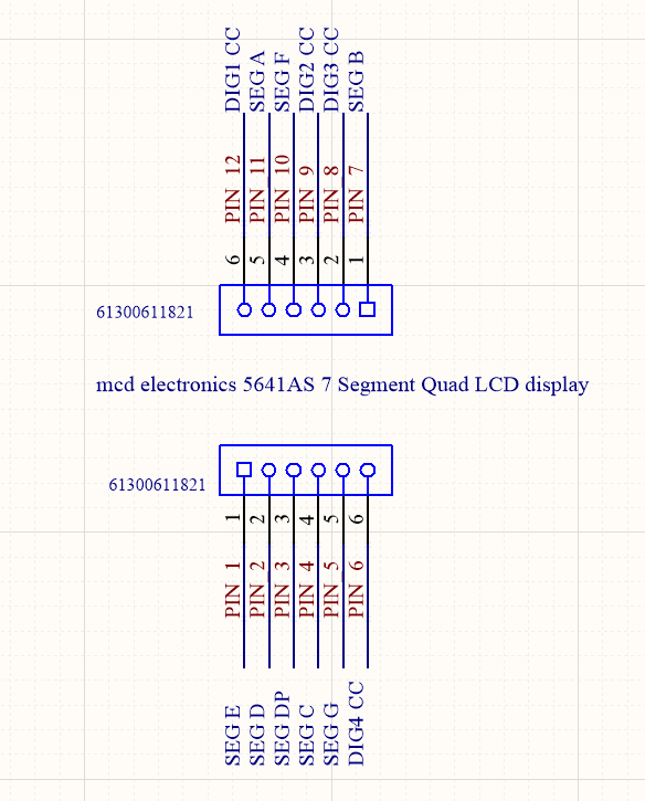
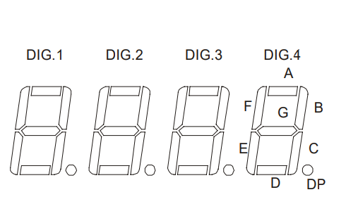
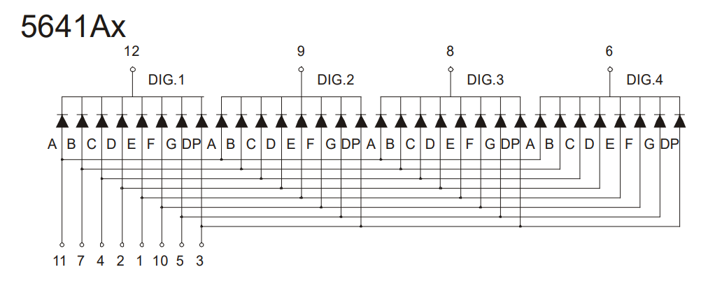
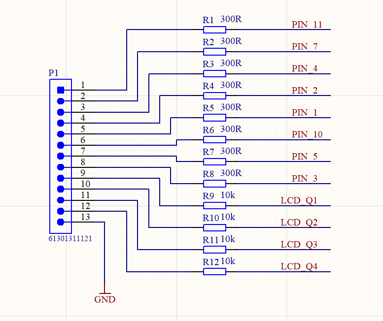
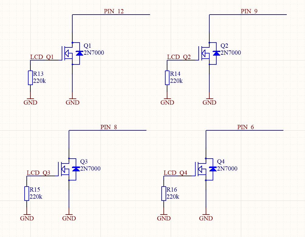
HardwareFor the needs of this project, I created a hand made PCB for the 5641AS quad digit 7-segment LED display. The segments line are connected to header through 300 ohms resistors, the common cathodes of each display are driven by 2N7000 N-MOS transistors whose gates are connected to header by 10 k ohm resistors and grounded by 220 k ohm resistors. A 13-pin header (8 segments, 4 common cathodes, 1 GND) is connected to the MiniZed via an Arduino connector.
Schematics of the board and internal connections of LED display are attached. However you can use other display and board with similar hardware.
Creating VHDL 7-Segment LCD Display DriverI started with a block diagram. Input data is a 16-bit number where every 4 bits being the number of one of the displays, so the least significant 4 bits are number on first display from right and consecutive 4 bits are next display, up to 4 most significant bits which are number on 4th display from left. So 16-bit binary number 0b0011001000010000 will show on display 3210. Second 4-bit input is for displaying decimal precision, where least significant bit is dot on first display from left and most significant bit is 4th display from left. So 4-bit binary number 0b0001 will show dot on only first display from left. Other inputs are clock and reset, the module is designed for a default 50 MHz clock and provide a result with a display refresh rate of about 800Hz (200 Hz for each number).
selector.vhd
This module divides the frequency and controls multiplexers with a 2-bit output address 00 for the first display and 11 for the last display.
library IEEE;
use IEEE.STD_LOGIC_1164.ALL;
-- Uncomment the following library declaration if using
-- arithmetic functions with Signed or Unsigned values
use IEEE.NUMERIC_STD.ALL;
-- Uncomment the following library declaration if instantiating
-- any Xilinx leaf cells in this code.
--library UNISIM;
--use UNISIM.VComponents.all;
entity selector is
Port
(
clk, reset: in std_logic;
sel: out std_logic_vector(1 downto 0)
);
end selector;
architecture Behavioral of selector is
signal state, next_state: unsigned(17 downto 0);
begin
--register
process(clk, reset)
begin
if reset='1' then
state <= (others=>'0');
elsif (clk'event and clk='1') then
state <= next_state;
end if;
end process;
--next state logic
next_state <= state + 1;
--output clk/2^16 for 50MHz around 800 Hz out
sel <= std_logic_vector(state(17 downto 16));
end Behavioral;
mux_4_to_1.vhd
This module sets dot segment on the currently controlled LED display.
library IEEE;
use IEEE.STD_LOGIC_1164.ALL;
-- Uncomment the following library declaration if using
-- arithmetic functions with Signed or Unsigned values
--use IEEE.NUMERIC_STD.ALL;
-- Uncomment the following library declaration if instantiating
-- any Xilinx leaf cells in this code.
--library UNISIM;
--use UNISIM.VComponents.all;
entity mux_4_to_1 is
Port
(
input  : in std_logic_vector (3 downto 0);
sw     : in std_logic_vector (1 downto 0);
output : out std_logic
);
end mux_4_to_1;
architecture Behavioral of mux_4_to_1 is
begin
with sw select
output <=
input(0)  when "00",
input(1)  when "01",
input(2)  when "10",
input(3)  when "11",
'0' when others;
end Behavioral;
mux_16_to_1.vhd
This module sets the 4-bit output from 16-bit input for the currently controlled LED display.
library IEEE;
use IEEE.STD_LOGIC_1164.ALL;
-- Uncomment the following library declaration if using
-- arithmetic functions with Signed or Unsigned values
--use IEEE.NUMERIC_STD.ALL;
-- Uncomment the following library declaration if instantiating
-- any Xilinx leaf cells in this code.
--library UNISIM;
--use UNISIM.VComponents.all;
entity mux_16_to_4 is
Port
(
input  : in std_logic_vector (15 downto 0);
sw     : in std_logic_vector (1 downto 0);
output : out std_logic_vector (3 downto 0)
);
end mux_16_to_4;
architecture Behavioral of mux_16_to_4 is
begin
with sw select
output(3 downto 0) <=
input(3 downto 0)   when "00",
input(7 downto 4)   when "01",
input(11 downto 8)  when "10",
input(15 downto 12) when "11",
"0000" when others;
end Behavioral;
hex4b_to_lcd.vhd
Converts 4-bit input data to output for the currently controlled LED display.
library IEEE;
use IEEE.STD_LOGIC_1164.ALL;
-- Uncomment the following library declaration if using
-- arithmetic functions with Signed or Unsigned values
--use IEEE.NUMERIC_STD.ALL;
-- Uncomment the following library declaration if instantiating
-- any Xilinx leaf cells in this code.
--library UNISIM;
--use UNISIM.VComponents.all;
entity hex4b_to_lcd is
Port
(
input:  in  std_logic_vector(3 downto 0);
dot:    in  std_logic;
output: out std_logic_vector(7 downto 0)
);
end hex4b_to_lcd;
architecture Behavioral of hex4b_to_lcd is
begin
with input select
output(6 downto 0) <=
"0111111" when "0000",
"0000110" when "0001",
"1011011" when "0010",
"1001111" when "0011",
"1100110" when "0100",
"1101101" when "0101",
"1111101" when "0110",
"0000111" when "0111",
"1111111" when "1000",
"1101111" when "1001",
"1110111" when "1010", --a
"1111100" when "1011", --b
"0111001" when "1100", --c
"1011110" when "1101", --d
"1111001" when "1110", --e
"1110001" when others; --f
output(7) <= dot;
end Behavioral;
seg_mux_4.vhd
The module switches the currently used LED display.
library IEEE;
use IEEE.STD_LOGIC_1164.ALL;
-- Uncomment the following library declaration if using
-- arithmetic functions with Signed or Unsigned values
--use IEEE.NUMERIC_STD.ALL;
-- Uncomment the following library declaration if instantiating
-- any Xilinx leaf cells in this code.
--library UNISIM;
--use UNISIM.VComponents.all;
entity seg_mux_4 is
Port
(
input:  in  std_logic_vector (1 downto 0);
enable: in  std_logic;
output: out std_logic_vector (3 downto 0)
);
end seg_mux_4;
architecture Behavioral of seg_mux_4 is
begin
output <= "0000" when (enable = '0') else
"0001" when (input = "00") else
"0010" when (input = "01") else
"0100" when (input = "10") else
"1000" when (input = "11") else
"0000";
end Behavioral;
main.vhd
This is the top module which combines all of above modules into 7-segment display driver.
library IEEE;
use IEEE.STD_LOGIC_1164.ALL;
-- Uncomment the following library declaration if using
-- arithmetic functions with Signed or Unsigned values
--use IEEE.NUMERIC_STD.ALL;
-- Uncomment the following library declaration if instantiating
-- any Xilinx leaf cells in this code.
--library UNISIM;
--use UNISIM.VComponents.all;
entity main is
Port
(
clk:       in std_logic;
dat_in:    in std_logic_vector(15 downto 0);
dp:        in std_logic_vector(3 downto 0);
reset    : in std_logic;
lcd_out:    out std_logic_vector (7 downto 0);
seg_out:    out std_logic_vector (3 downto 0)
);
end main;
architecture Behavioral of main is
signal num_sel: std_logic_vector (1 downto 0);
signal num_out: std_logic_vector (3 downto 0);
signal dp_out:  std_logic;
begin
u1: entity work.selector
port map(clk=>clk, reset=>reset, sel=>num_sel);
u2: entity work.mux_16_to_4
port map(input=>dat_in, sw=>num_sel, output=>num_out);
u3: entity work.seg_mux_4
port map(input=>num_sel, enable=>'1', output=>seg_out);
u4: entity work.mux_4_to_1
port map(input=>dp, sw=>num_sel, output=>dp_out);
u5: entity work.hex4b_to_lcd
port map(input=>num_out, dot=>dp_out, output=>lcd_out);
end Behavioral;
VHDL code files for all modules are included for use and analysis.
Implementation of VHDL module into Mini But Mighty project
So the module was created using VHDL, but how to test it on a MiniZed board? Larger FPGA boards often have 8 or 16 input switches and LEDs for testing inputs and outputs of hardware modules implemented in programmable logic. OK, we don't have enough LEDs and switches on the MiniZed board, but we have something more, Zynq 7000 SoC which have an ARM Cortex - A9 processor system (PS) and Xilinx Artix programmable logic (PL). We can use and combine this resources to create a flexible test environment inside the chip and have as many inputs and outputs as we need. This will be presented by implementing created VHDL module into Mini But Mighty project.
The starting point will be the Mini But Mighty project.
The first step is to add our created sources to the project. To do that we use tab sources and the "plus" button.
In the next step we choose "Add or create design sources".
Then click on "Add Files" button.
And we choose our VHDL files and click "OK".
Now in add source window we see our VHDL files. Make sure that "Copy sources into project" is selected, then accept the added sources and go to the next step.
Sources window should look like that.
Now click right mouse button on empty place in block space and choose "add module".
In new window choose "main.vhd" and click "OK".
Now in the block design we see created VHDL module.
This module is simple RTL block and we need some I/O to use it. We will use axi_gpio IP, but first we need to configure the Processing system. To do that double click on the Zynq block and choose PS-PL configuration tab.
Click "Axi Non Secure Enablement", followingly "GP Master AXI Interface" and select "M AXI GP0 interface" and confirm the changes.
Adding AXI GPIO IP is done by clicking the "plus" button in the block design, typing"gpio" in the search window and selecting "AXI GPIO".
We need also the two "slice" blocks so repeat the last step two times typing "slice" in the search box.
Now we have all the elements and we need to configure some of them. First AXI GPIO, set manually 20-bit width in the IP settings configuration tab.
Configure the 1st slice for 20-bit input width and 15 to 0 output, and the 2nd for 20-bit input width and 19 to 16 output.
All blocks are configured, so connections between them should be established. To do this, first click on "Run connection automation".
And select the "All automation" (FCLK0 is default configured on 50MHz and its the required input frequency for our RTL block).
By default Vivado will connect VHDL module reset to peripheral_aresten, we need to correct this and connect reset to the peripheral_reset.
Now we connect slice blocks to axi_gpio_0 and slice outputs to according RTL module inputs.
Last step is to make RTL module outputs external and save block design. The final block design is below.
Before implementation, synthesis and bitstream generating, constraints must be modified. Common segments of the display are connected to Arduino IO0 to IO7 and common cathodes of each display are connected to IO8 to IO11. Therefore we have to add following lines in io.xdc file.
set_property PACKAGE_PIN R8  [get_ports {lcd_out_0[7]}];  # "R8.ARDUINO_IO0"
set_property PACKAGE_PIN P8  [get_ports {lcd_out_0[6]}];  # "P8.ARDUINO_IO1"
set_property PACKAGE_PIN P9  [get_ports {lcd_out_0[5]}];  # "P9.ARDUINO_IO2"
set_property PACKAGE_PIN R7  [get_ports {lcd_out_0[4]}];  # "R7.ARDUINO_IO3"
set_property PACKAGE_PIN N7  [get_ports {lcd_out_0[3]}];  # "N7.ARDUINO_IO4"
set_property PACKAGE_PIN R10 [get_ports {lcd_out_0[2]}];  # "R10.ARDUINO_IO5"
set_property PACKAGE_PIN P10 [get_ports {lcd_out_0[1]}];  # "P10.ARDUINO_IO6"
set_property PACKAGE_PIN N8  [get_ports {lcd_out_0[0]}];  # "N8.ARDUINO_IO7"
set_property PACKAGE_PIN M9  [get_ports {seg_out_0[0]}];  # "M9.ARDUINO_IO8"
set_property PACKAGE_PIN N9  [get_ports {seg_out_0[1]}];  # "N9.ARDUINO_IO9"
set_property PACKAGE_PIN M10 [get_ports {seg_out_0[2]}];  # "M10.ARDUINO_IO10"
set_property PACKAGE_PIN M11 [get_ports {seg_out_0[3]}];  # "M11.ARDUINO_IO11"
set_property IOSTANDARD LVCMOS33 [get_ports -of_objects [get_iobanks 34]];
Once the wrapper and constraints are created, we are in a position to implement the design. Select the Generate BitStream Option and wait a few minutes while the design compiles.
Implementing the design
Once the bit stream is available, the next step is to export the XSA for use in Vitis. Under file select Export-> Export Hardware.
Exporting the hardware
In the dialog box which is presented select the include bitstream option
Exporting the XSA
We are now ready to open Vitis and update software application
Vitis Software BuildUse the "tools" tab to launch Vitis and select Mini But Mighty Workspace. Now we have to update the hardware platform. Click right mouse button on design_1_wrapper and choose Update Hardware Specification.
In the newly opened window, select updated XSA file and confirm.
Click the build button and wait for the end of the compilation, then open platform.spr file to check the configuration, axi_gpio_0 should be in Hardware Specification Address Map for processor list.
Now we will modify the helloworld.c application to display actual PWM on our display. First we need to include additional libraries for AXI GPIO:
#include "xparameters.h"
#include "xgpio.h"
and defines:
#define GPIO_EXAMPLE_DEVICE_ID  XPAR_GPIO_0_DEVICE_ID
#define GPIO_CHANNEL 1
and GPIO driver instance:
XGpio GpioPL; /* The Instance of the GPIO Driver */Our 7-segment LED display and hardware driver module are by default adjusted for hexadecimal numbers. So then we need to create a function that will provide easy use of decimal numbers in our software application:
uint8_t set_7seg_dec(uint16_t dec_num, uint8_t dp)
{
uint32_t seg7_out;
seg7_out = 0; // set 0 output
seg7_out = dp<<16; // set decimal point
seg7_out  |= (seg7_out & LED_MASK) | (dec_num % 10)*0x01;
seg7_out  |= (seg7_out & LED_MASK) | (dec_num / 10)%10*0x10;
seg7_out  |= (seg7_out & LED_MASK) | (dec_num / 100)%10*0x100;
seg7_out  |= (seg7_out & LED_MASK) | (dec_num / 1000)%10*0x1000;
XGpio_DiscreteWrite(&GpioPL, GPIO_CHANNEL, seg7_out);
return 0;
}
dec_num - is 16-bit unsigned int number,
dp - is 8-bit usigned int number which 4 least significant bits are used for decimal point e.g. decimal 2 = 0b00000010 will display dot on the second display form right.
LED_MASK is 0x0000FFFF hex number and its used for masking decimal point part of the 32-bit seg7_out variable.
The last thing to do is to modify function which is used to set the output PWM duty cycle. We do this by adding set_7seg_function to the set_pwm function and using the "cycle" variable. Variable is multiplied by ten because we set the decimal point on the second display :
void set_pwm(u32 cycle) {
u32 MatchValue;
set_7seg_dec(cycle*10, 2);
MatchValue = (TimerSetup->Interval * cycle) / 100;
XTtcPs_SetMatchValue(&ttcTimer, 0, MatchValue);
}
A Full code of modified helloworld.c is below, the file is also available on the github repository.
#include <stdio.h>
#include "platform.h"
#include "xparameters.h"
#include "xil_printf.h"
#include "xgpiops.h"
#include "sleep.h"
#include "xil_exception.h"
#include "xttcps.h"
#include "xscugic.h"
#include "xgpio.h"
/*
* The following constants map to the XPAR parameters created in the
* xparameters.h file. They are defined here such that a user can easily
* change all the needed parameters in one place.
*/
#define GPIO_EXAMPLE_DEVICE_ID  XPAR_GPIO_0_DEVICE_ID
/*
* The following constant is used to determine which channel of the GPIO is
* used for the LED if there are 2 channels supported.
*/
#define GPIO_CHANNEL 1
/*
* The following constant is used to wait after an LED is turned on to make
* sure that it is visible to the human eye.  This constant might need to be
* tuned for faster or slower processor speeds.
*/
#define LOOP_DELAY     1000000
#define LED_MASK 0x0FFFF
#define GPIO_DEVICE_ID  	XPAR_XGPIOPS_0_DEVICE_ID
#define INTC_DEVICE_ID		XPAR_SCUGIC_0_DEVICE_ID
#define	TICK_TIMER_FREQ_HZ	100
#define TTC_TICK_DEVICE_ID	XPAR_XTTCPS_0_DEVICE_ID
#define TTC_TICK_INTR_ID	XPAR_XTTCPS_0_INTR
static void TickHandler(void *CallBackRef);
int SetupTicker(XTtcPs *TtcPsInst, u16 DeviceID, u16 TtcTickIntrID,
XScuGic *InterruptController);
static int SetupInterruptSystem(u16 IntcDeviceID, XScuGic *IntcInstancePtr);
int SetupTimer(u16 DeviceID, XTtcPs *TtcPsInst);
void set_pwm(u32 cycle);
void display_menu();
typedef struct {
u32 OutputHz; /* Output frequency */
XInterval Interval; /* Interval value */
u8 Prescaler; /* Prescaler value */
u16 Options; /* Option settings */
} TmrCntrSetup;
/*
* The following are declared globally so they are zeroed and so they are
* easily accessible from a debugger
*/
XGpio GpioPL; /* The Instance of the GPIO Driver */
XGpioPs Gpio;
XGpioPs_Config *ConfigPtr;
XTtcPs_Config *TtcConfig;
XTtcPs ttcTimer;
TmrCntrSetup *TimerSetup;
XScuGic InterruptController; /* Interrupt controller instance */
XTtcPs TtcPsInst;
u32 MatchValue;
static TmrCntrSetup SettingsTable = { TICK_TIMER_FREQ_HZ, 0, 0, 0 };
uint8_t set_7seg_dec(uint16_t dec_num, uint8_t dp)
{
uint32_t seg7_out;
seg7_out = 0; // set 0 output
seg7_out = dp<<16; // set decimal point
seg7_out  |= (seg7_out & LED_MASK) | (dec_num % 10)*0x01;
seg7_out  |= (seg7_out & LED_MASK) | (dec_num / 10)%10*0x10;
seg7_out  |= (seg7_out & LED_MASK) | (dec_num / 100)%10*0x100;
seg7_out  |= (seg7_out & LED_MASK) | (dec_num / 1000)%10*0x1000;
XGpio_DiscreteWrite(&GpioPL, GPIO_CHANNEL, seg7_out);
return 0;
}
int main() {
u8 DutyCycle;
char key_input;
int Status;
volatile int Delay;
uint32_t byte, l_byte;
uint32_t lcd_dec=0;
init_platform();
TmrCntrSetup SettingsTable = { TICK_TIMER_FREQ_HZ, 0, 0, 0 };
ConfigPtr = XGpioPs_LookupConfig(GPIO_DEVICE_ID);
XGpioPs_CfgInitialize(&Gpio, ConfigPtr, ConfigPtr->BaseAddr);
XGpioPs_SetDirectionPin(&Gpio, 54, 1);
XGpioPs_SetOutputEnablePin(&Gpio, 54, 1);
XGpioPs_WritePin(&Gpio, 54, 0x1);
printf("www.adiuvoengineering.com\n\r");
printf("DC Motor Control Example\n\r");
SetupInterruptSystem(INTC_DEVICE_ID, &InterruptController);
SetupTicker(&ttcTimer, TTC_TICK_DEVICE_ID, TTC_TICK_INTR_ID,
&InterruptController);
byte = 0x20000;
/* Initialize the GPIO driver */
Status = XGpio_Initialize(&GpioPL, GPIO_EXAMPLE_DEVICE_ID);
if (Status != XST_SUCCESS) {
xil_printf("Gpio Initialization Failed\r\n");
return XST_FAILURE;
}
print("Write byte.\n\r");
/* Set the direction for all signals as  output */
XGpio_SetDataDirection(&GpioPL, GPIO_CHANNEL, 0x00);
/* Write inital data */
XGpio_DiscreteWrite(&GpioPL, GPIO_CHANNEL, byte);
//	while (1) {
//
//		if (lcd_dec == 1000) lcd_dec = 0;
////		byte = 0x20000;
//		lcd_dec ++;
//		set_7seg_dec(lcd_dec, 0x02);
////		byte |= (byte & 0x0ffff) | (lcd_dec % 10)*0x01;
////		byte |= (byte & 0x0ffff) | (lcd_dec / 10)%10*0x10;
////		byte |= (byte & 0x0ffff) | (lcd_dec / 100)%10*0x100;
////		byte |= (byte & 0x0ffff) | (lcd_dec / 1000)%10*0x1000;
////
////
////		XGpio_DiscreteWrite(&GpioPL, GPIO_CHANNEL, byte);
//
//
////		byte = inbyte(); // get byte from stdin (uart1)
////
////		if(l_byte != byte)
////		{
////			/* Set counter as output value of port */
////			XGpio_DiscreteWrite(&Gpio, LED_CHANNEL, byte);
////			/*Send byte to stdout*/
////			xil_printf("0x%02x\r\n", byte);
////			/*Save last value*/
////			l_byte = byte;
////		}
//
////		/* Wait a small amount of time so the LED is visible */
////		for (Delay = 0; Delay < LED_DELAY; Delay++);
////
////		/* Clear the LED bit */
////		XGpio_DiscreteClear(&Gpio, LED_CHANNEL, LED);
//
//		/* Wait a small amount of time  */
//		for (Delay = 0; Delay < LOOP_DELAY; Delay++);
//	}
while (1) {
display_menu();
read(1, (char*) &key_input, 1);
printf("Echo %c\n\r", key_input);
switch (key_input) {
//			case 0: // forward
//
//				set_pwm(0);
//				usleep(1000000);
//
//				set_pwm(DutyCycle);
//			break;
//			case 1: //reverse
//
//				//set_pwm(0);
//				//usleep(1000000);
//				//XGpioPs_WritePin(&Gpio, 54, 0x1);
//				//set_pwm(DutyCycle);
//			break;
case '1': //stop
set_pwm(0);
break;
case '2': //25%
printf("25%\n\r");
DutyCycle = 25;
set_pwm(DutyCycle);
break;
case '3': //33%
DutyCycle = 33;
set_pwm(DutyCycle);
break;
case '4': //50%
DutyCycle = 50;
set_pwm(DutyCycle);
break;
case '5': //66%
DutyCycle = 66;
set_pwm(DutyCycle);
break;
case '6': //75%
DutyCycle = 75;
set_pwm(DutyCycle);
break;
case '7': //100%
DutyCycle = 100;
set_pwm(DutyCycle);
break;
}
}
cleanup_platform();
return 0;
}
void display_menu() {
//Clear the screen
printf("\033[2J");
//Display the main menu
printf("*******************************************\n");
printf("****      www.adiuvoengineering.com    ****\n");
printf("****      Motor Control Example        ****\n");
printf("*******************************************\n");
printf("\n");
printf("   MM10 Motor Control   \n");
printf("------------------------------------------\n");
printf("\n");
printf("Select a Speed:\n");
printf("  (1)   - Stop\n");
printf("  (2)   - 25%\n");
printf("  (3)   - 33%\n");
printf("  (4)   - 50%\n");
printf("  (5)   - 66%\n");
printf("  (6)   - 75%\n");
printf("  (7)   - 100%\n");
printf("\n");
}
void set_pwm(u32 cycle) {
u32 MatchValue;
set_7seg_dec(cycle*10, 2);
MatchValue = (TimerSetup->Interval * cycle) / 100;
XTtcPs_SetMatchValue(&ttcTimer, 0, MatchValue);
}
int SetupTicker(XTtcPs *TtcPsInst, u16 DeviceID, u16 TtcTickIntrID,
XScuGic *InterruptController) {
int Status;
TmrCntrSetup *TimerSetup;
XTtcPs *TtcPsTick;
TimerSetup = &SettingsTable;
TimerSetup->Options |= (XTTCPS_OPTION_INTERVAL_MODE |
XTTCPS_OPTION_MATCH_MODE | XTTCPS_OPTION_WAVE_POLARITY);
Status = SetupTimer(DeviceID, TtcPsInst);
if (Status != XST_SUCCESS) {
return Status;
}
TtcPsTick = TtcPsInst;
Status = XScuGic_Connect(InterruptController, TtcTickIntrID,
(Xil_InterruptHandler) TickHandler, (void *) TtcPsTick);
if (Status != XST_SUCCESS) {
return XST_FAILURE;
}
XScuGic_Enable(InterruptController, TtcTickIntrID);
XTtcPs_EnableInterrupts(TtcPsTick, XTTCPS_IXR_INTERVAL_MASK);
XTtcPs_Start(TtcPsTick);
return Status;
}
static int SetupInterruptSystem(u16 IntcDeviceID, XScuGic *IntcInstancePtr) {
int Status;
XScuGic_Config *IntcConfig;
IntcConfig = XScuGic_LookupConfig(IntcDeviceID);
if (NULL == IntcConfig) {
return XST_FAILURE;
}
Status = XScuGic_CfgInitialize(IntcInstancePtr, IntcConfig,
IntcConfig->CpuBaseAddress);
if (Status != XST_SUCCESS) {
return XST_FAILURE;
}
Xil_ExceptionRegisterHandler(XIL_EXCEPTION_ID_IRQ_INT,
(Xil_ExceptionHandler) XScuGic_InterruptHandler, IntcInstancePtr);
Xil_ExceptionEnable();
return XST_SUCCESS;
}
int SetupTimer(u16 DeviceID, XTtcPs *TtcPsInst) {
int Status;
XTtcPs_Config *Config;
XTtcPs *Timer;
TmrCntrSetup *TimerSetup;
TimerSetup = &SettingsTable;
Timer = TtcPsInst;
Config = XTtcPs_LookupConfig(DeviceID);
if (NULL == Config) {
return XST_FAILURE;
}
Status = XTtcPs_CfgInitialize(Timer, Config, Config->BaseAddress);
if (Status != XST_SUCCESS) {
return XST_FAILURE;
}
XTtcPs_SetOptions(Timer, TimerSetup->Options);
XTtcPs_CalcIntervalFromFreq(Timer, TimerSetup->OutputHz,
&(TimerSetup->Interval), &(TimerSetup->Prescaler));
XTtcPs_SetInterval(Timer, TimerSetup->Interval);
XTtcPs_SetPrescaler(Timer, TimerSetup->Prescaler);
return XST_SUCCESS;
}
static void TickHandler(void *CallBackRef) {
u32 StatusEvent;
/*
* Read the interrupt status, then write it back to clear the interrupt.
*/
StatusEvent = XTtcPs_GetInterruptStatus((XTtcPs * )CallBackRef);
XTtcPs_ClearInterruptStatus((XTtcPs * )CallBackRef, StatusEvent);
//printf("timer\n\r");
/*update the flag if interrupt has been occurred*/
//UpdateFlag = TRUE;
}
Afterwards we have to save the file and build the project.
Then, if there is no errors, click the "run" button and try typing number in terminal to change pulse width on Pmod HB3 output. The actual duty cycle will be shown on the 7-segment LED display.
This project has shown by example of quad 7-segment LED display and update of the Mini But Mighty project, how we can use our own VHDL or other HDL modules into Vivado and Vitis using AXI GPIO IP. The combination of programmable logic and processing system is powerful and only limit is imagination. You can use same approach for another HDL modules.


Comments