
Hardware components | ||||||
 |
| × | 1 | |||
 |
| × | 1 | |||
Software apps and online services | ||||||
 |
| |||||
Hand tools and fabrication machines | ||||||
 |
| |||||
 |
| |||||
Recently I received an AVR-IoT WG development board for the Smart Medical Design Challenge sponsored by Microchip.
When first trying to program the device, the Atmel Studio IDE prompted me to update the firmware of the on-board nEDBG debugger. Unfortunately, the debugger failed to be detected afterwards and remained stuck in bootloader mode.
I tried to restore the firmware many times but to no avail. After attempting for days, I decided to use an external programmer instead.
UPDI Programming InterfaceOn the AVR-IoT WG Board, is the Atmega4808 Microcontroller. It requires Unified Program and Debug Interface (UPDI) to program the chip. Many of the newer ATmega and ATtiny microcontrollers also use UPDI.
The Unified Program and Debug Interface (UPDI) is a one-wire interface for external programming and on-chip debugging of newer ATtiny and ATmega devices.
Because it requires only one wire, it is very easy for us to hook it up.
nEDBG debuggerAs there are no debugging pins broken out on the board, let's first take a look at the schematic to plan where we need to solder.
The nEDBG has 3 interfaces which are the UPDI debugger, a USB CDC Virtual COM Port and a Data Gateway Interface (DGI).
We will only be soldering one wire for the UPDI so it's important to know that if we use the UPDI externally, we will not have access to the CDC and DGI interface.
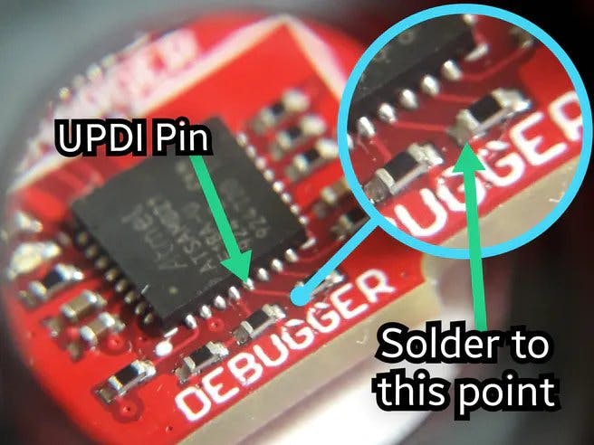
Preparing the AVR-IoT BoardThe UDPI signal is directly connected to pin 5 of the on-board debugger and resistor R110.
On the actual board, this is the point to solder.
Please be careful when soldering as that area is very tight in space. Note that the resistor is a 0402 package size and is very small.
As in this photo, I used 26AWG wire which is small enough to fit.
And from here on, you can connect that wire to your UPDI programmer.
Arduino as UPDI programmmerFor those on a budget, thankfully we can use the open-source project, jtag2updi. It is a piece of code that converts any Arduino (Uno/Nano) into a UPDI programmer.
Download this github repository to your PC first
Open up jtag2updi.ino in Arduino IDE and flash it to the Arduino Nano board.
From here on, the Arduino Nano will act as a programmer
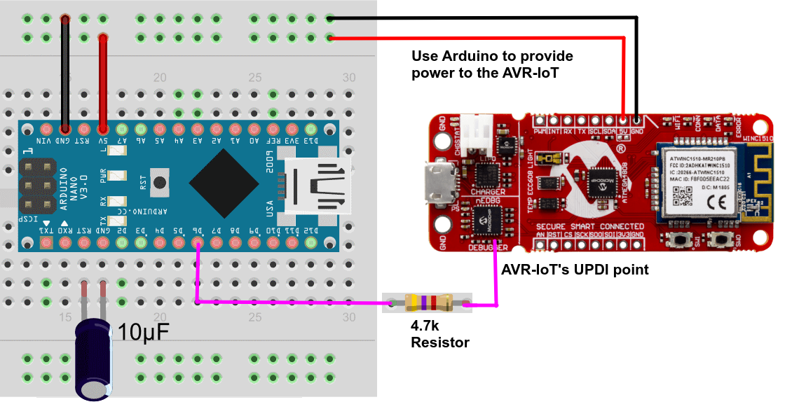
To program the AVR-IoT, we need to make some connections.
- Wire up the Arduino D6 with a 4.7k resistor to AVR-IoT's UPDI point
- Wire up the Arduino 5V/Gnd to the AVR-IoT's 5V/Gnd
- Add 10uF capacitor between Arduino RST and GND. (Reason is to prevent auto-reset when acting as a programmer)
If needed, you can connect an external serial to USB converter to the RX/TX pins.
Verify connectivityTo check if the device is being detected correctly, we will make use of a command line tool called avrdude.
The Arduino software also comes with avrdude bundled together. It is found at "C:\Program Files (x86)\Arduino\hardware\tools\avr\bin".
In the jtag2updi folder, find avrdude.conf.
Copy the file .\avrdude.confinto the folder C:\Program Files (x86)\Arduino\hardware\tools\avr\bin
In this folder, do a Shift+Right Click and choose "Open command window here".
Run this command. Be sure to change COM4 to your COM port of the device. You can check which COM port number it is in the device manager.
avrdude -C .\avrdude.conf -c jtag2updi -P COM4 -p m4808This command will read the device signature and we can confirm that it is the correct microcontroller
Subsequently, you can also build hex files from Atmel Studio and program it using avrdude with this command
avrdude -C .\avrdude.conf -c jtag2updi -P COM4 -p m4808 -U flash:w:"AVRIoTWGSensorNode.hex":iFor demonstration purposes, I will show how to program the AVR-IoT WG Board using Arduino IDE.
First, install the board files to program the ATmega4808.
We will use MegaCoreX by MCUDude
In the Arduino IDE, open File > Preferences and add this URL into the Additional Boards Manager URLs:
https://mcudude.github.io/MegaCoreX/package_MCUdude_MegaCoreX_index.jsonInstall MegaCoreX in Tools > Board > Boards Manager
Set the board to ATmega4808 for the AVR-IoT WG Board.
And select JTAG2UPDI as the programmer.
That's it for now! You can upload any sketch to confirm everything works!
I have attached an example blinky LED code for you to try out!


Comments