


Hardware components | ||||||
 |
| × | 1 | |||
| × | 1 | ||||
Welcome to the first hardware hack night! Tonight's free hardware giveaway consists of a strand of 5 WS2812 addressable RGB LEDs and an Arduino Nano clone for controlling the lights. Listed below is basic information on setting up the hardware and a simple project that gives you the ability to control the color of each individual pixel using the serial port. Remember, this is just start - there's plenty of loaner hardware available so you can make some awesome creations. Some ideas:
- Use APIs from Facebook, Twitter, Instagram, etc... to monitor when your friends post something new and then light up the strand as a notification.
- Integrate the strand into your CI or Testing server. Have it change color to represent the status of your build/tests.
- Hook up one of the analog gas detection sensors and use the leds as output for monitoring the levels of CO2, methane, etc...
- Use a breadboard and some buttons to make a "Simon" like game!
- Create your own "DreamScreen" and add ambient LED lighting to your laptop
To keep costs down, I used an Arduino Nano clone. Since the cost of an FTDI usb-serial chip is pretty high compared to the other components, these boards use a CH340G usb-serial chip. Unfortunately, most operating systems don't come with the driver preinstalled so you'll have to manually install it.
- MacOS: Download the driver installer (<=10.11 will crash Sierra) or driver (safe for Sierra) and run the CH34x_Install.pkg to install the driver. It'll appear as /dev/cu.wchusbserialXXXX.
- Windows: Open Device Manager, and then select the "USB 2.0-Serial". Right click and select "Update driver". Windows should be able to find a CH340G driver in its database.
Our LEDs are WS2812 individually addressable RGB Light Emitting Diodes. They have three connections, power, ground, and signal. The signal to control the LEDs is very timing dependent - but no worries, a library has already been written so we can start blinking some lights right away. To install the library, first select the "Manage Libraries" option from the Sketch > Include Library dropdown.
Then, search for the Adafruit NeoPixel library and install it!
This library is really terrific for controlling the LEDs. The Fast LED library is another library that we could use to control our pixels and it's installed in a similar fashion as the Adafruit NeoPixel library.
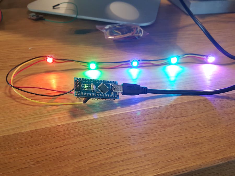
Assemble HardwareThis is super simple. Make sure the Arduino clone is unplugged. First, plug the power and ground from the strip (red is power, black is ground) into the pins marked +5V and GND respectively.
Then, plug the signal wire (yellow) onto the pin labeled D2. You can use any of the output pins, but you'll have to modify the code to match the pin number.
That's it!. Once you plug in your USB cable, a pre-built demo showing off the pixels should start. Look at those blinky LEDs!
Serial LED Control CodeAttached below is a simple sketch that allows you to manually set the color of each pixel individually using the serial port. It's simple enough, but we'll do a basic walkthrough here...
#include <Adafruit_NeoPixel.h>
#define PIN 2 //LED PIN Location
#define NUM_LEDS 5 //number of leds
int inputCount = 0;
int serialArr[4];
Adafruit_NeoPixel strip = Adafruit_NeoPixel(NUM_LEDS, PIN, NEO_GRB + NEO_KHZ800);
In this first bit, we include the NeoPixel library, and define the location and number of leds on our strip. Change the value for PIN if you're not using D2 for the led signal. Next, we create an integer to keep track of the number of integers we receive over the serial port and an array to store these values. Finally, we create an instance of a NeoPixel strip, using the values we setup earlier.
void setup() {
 // setup pixel strip and show() nothing
 strip.begin();
 strip.show();
 //start serial port at 115200 bps
 Serial.begin(115200);
}
The setup() function is pretty simple, we setup the pixel strip and clear it out by calling strip.show()
with no values being set. Then, we start the Serial port at 115,200 bps.
void loop() {
 //send (pixel, R, G, B) over serial
 //lights pixel with color
 if (inputCount == 4){
   inputCount = 0;
   strip.setPixelColor(serialArr[0], serialArr[1], serialArr[2], serialArr[3]);
   strip.show();
 } else {
 // read bytes from serial
   while(Serial.available()>0)
   {
     int input = Serial.parseInt();
     serialArr[inputCount] = input;
     inputCount++;
   }
 }
}
And our loop() function checks to see if we received the correct number of integers to set a pixel. If not, we wait for input from the serial port. Once we have the pixel number, and values for the R, G, and B leds, we use the strip.setPixelColor()
function to set the individual pixels color. Then we use the strip.show()
function to change the color of the pixel. Simple!

Comments