


Hardware components | ||||||
 |
| × | 1 | |||
 |
| × | 2 | |||
| × | 1 | ||||
| × | 1 | ||||
 |
| × | 3 | |||
| × | 1 | ||||
 |
| × | 1 | |||
| × | 1 | ||||
 |
| × | 1 | |||
Software apps and online services | ||||||
_4YUDWziWQ8.png?auto=compress%2Cformat&w=48&h=48&fit=fill&bg=ffffff) |
| |||||
 |
| |||||
| ||||||
| ||||||
 |
| |||||
Hand tools and fabrication machines | ||||||
 |
| |||||
 |
| |||||
 |
| |||||
 |
| |||||
 |
| |||||
 |
| |||||
|
| |||||
Contents :
- Introduction : Objectives, expectations
- Terms of reference
- Management : WBS and Gantt chart
- Research and documentation
- Hardware : Schematic explanation
- Software : Explanation of the Arduino code
- Data sending : Message size, Sigfox, Ubidots and BEEP
- PCB : Design, printing, adding components
- Boxing
- Aesthetic
- Conclusion
The objective of this project is to realize a connected system with sensors that allows to measure several physical quantities and to make them available through several Cloud platforms. Indeed, this project must allow to recover and format measured data and then send them on a server (Cloud) thanks to the long range and low power technology (LPWAN) of Sigfox. The data must be accessible in graphical form from a web interface on PC Desktop or Smartphone. The system must also be able to send alerts on smartphone (SMS or Mail) when abnormal behaviors are detected. The data collected is intended to analyze and provide information on the health status of bees and their productivity
🐝 Terms of referenceSpecifications :
The system is intended to collect and send the following data:
- The interior and exterior humidity:
o This information is important for the beekeeper, it allows him to predict and explain the behavior of the bees as well as their positions in the hive.
- The inside and outside temperature :
o This information is important for the beekeeper, it allows him to predict and explain the behavior of the bees as well as their positionings in the hive.
- The total weight of the hive :
o This information gives an indication of the quantity of honey and the number of bees in the hive. It also allows to detect a fall or a theft if the weight varies suddenly.
- The battery level to power the complete system:
o The battery level in percentage allows to indicate to the beekeeper the battery level. Indeed, this information allows to visualize if the quantity of consumed energy is superior to the one recovered thanks to the photovoltaic cell.
- The luminosity received by the photovoltaic cell:
o The luminosity allows to understand the contribution of energy thanks to the cell according to the luminosity. This information also gives an indication of the temperature.
The data collected and transmitted to the beekeeper must be clear and precise:
- The percentage of indoor and outdoor humidity: 2% accuracy (accuracy on 7 bits)
- The inside and outside temperature: Accuracy 0, 5 °C (accuracy on 10 bits)
- Total weight of the hive: Accuracy 100 g (18 bit accuracy)
- The battery level to power the whole system: 7-bit precision
- The luminosity received by the photovoltaic cell: 6 bits precision
All these data will be recovered by the following sensors:
- The percentage of interior and exterior humidity: DHT22
- The interior and exterior temperature: DHT22 and temperature probes
- The total weight of the hive: strain gauge (HX711)
- The luminosity received by the photovoltaic cell: Photoresistance
The sensors will be distributed as follows:
Inside the hive :
- 3 Groove DS18B20 temperature sensors, 2 at the ends and one in the center
- 1 DHT22 humidity sensor in the center of the hive
Outside the hive:
- 1 weight sensor on which the hive rests
- 1 temperature and humidity sensor DHT22
- The solar panel + photoresistance system placed at the top of the hive slightly inclined.
One of the specificities of this system is its autonomy.
Indeed, the objective is to associate a battery and a photovoltaic panel, thanks to a module lipo rider pro. This will ensure the autonomous operation of our system.
During the day, the system works with the energy provided by the solar panel. This one also stores in the battery. Finally, the battery will have enough energy to power the system outside the day.
🐝 ManagementHere are 2 tools used to organize our project: The Gantt chart and the WBS
A Gantt chart is a practical tool for planning projects. Thanks to an overview of the planned tasks, everyone involved knows which activity has to be done by which date.
A Gantt chart shows the start and end date of a project, the tasks associated with the project, the people assigned to each task etc...
The WBS consists of a division of the project into several tasks, which makes the work more accessible and more manageable.
In order to carry out the project, we started with a research and documentation session on the components to use. Here are some information that we have retained and considered useful.
Microcontroller MKR FOX 1200:
- Power supply via micro USB possible
- 3.3 to 5V output voltage
- 28 pins inputs/outputs.
Temperature sensor DS18B20 :
- Temperature from -55° to 125° C
- Water resistance
- +- 0.5°C of accuracy
Humidity and temperature sensor DHT22 :
- Humidity data from 0 to 100%.
- 2-5% accuracy for humidit
- Humidity data from -40° to 80°C
- +- 0.5°C of accuracy
HX711 Amplifier:
- 24-bit accuracy
Lipo Rider-Pro:
- 5v output voltage
- Output current of 1A max
Battery Li-Ion 3.7V :
- Voltage of 3.7V Vcc
- Current of 1mAh
Solar panel SOL2W :
- Output voltage of 6V at max light condition
- Current of 360 mAh
- Monocrystalline silicon
We had to make strategic component choices, especially for the resistors, in order to limit our system power consumption. For that, we performed several tests (using oscilloscope) and calculations, voltage dividers.
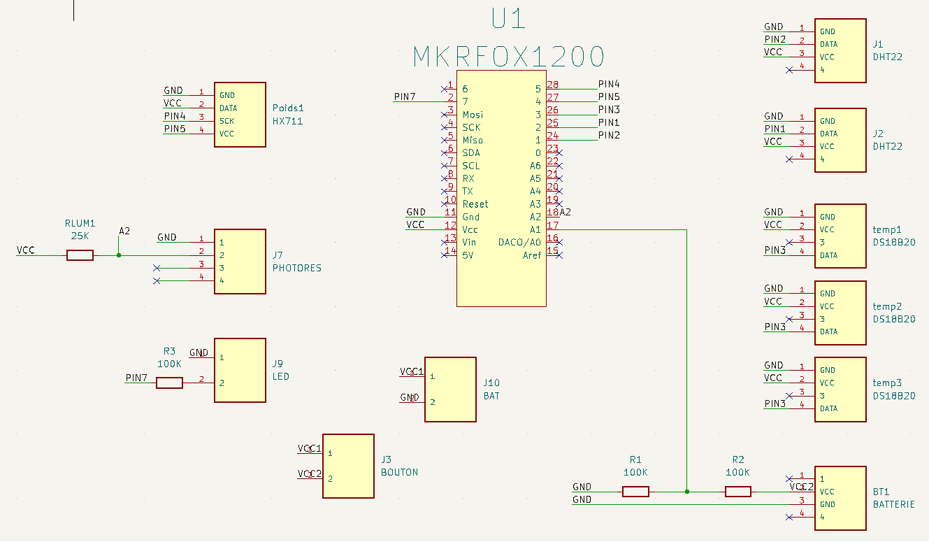
Once we had chosen all our components and sensors we were able to finalize the schematic by connecting them to the arduino MKR FOX 1200, using KiCAD software.
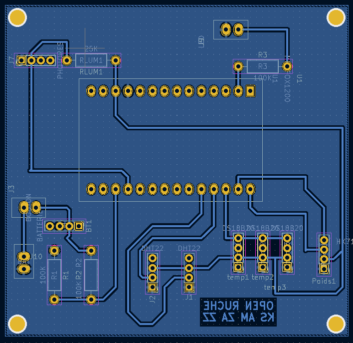
As soon as we were sure of our schematic (values, components, number of sensors), we moved on to routing and printing our PCB.
The Arduino board will allow to get the data from the sensors in order to prepare them for the export to Sigfox which will be done with an antenna and the Sigfox module present on the board. The sending of the data to Sigfox will be done every 10 minutes.
The recovery of the data as well as the preparation of these is managed by the Arduino code.
The complete script can be broken down into 3 parts:
1) Declaration of the libraries and variables used
2) Declaration of functions for each sensor/step (e.g.: 1 function for the weight, 1 function for sending data...)
3) void loop() which calls all functions and uses all previously declared variables
The data is sent through the SigFox module on the Arduino MKR 1200.
The Arduino board can only send 140 messages per day. Each message cannot be larger than 12 bytes or 96 bits.
In order to respect these criteria, we must concatenate the different data in a single variable as below :
Now we need to fill in the message structure on Sigfox to separate the data :
Here is how we inform Sigfox about the composition of the variable. This line of code will separate the data and retrieve it.
We made different holes on our box to simplify the passage of cables and to add the switch. Moreover, we have fixed "little feet" in order to have a support for the PCB.
Here you can see the final box we made.
In order to create a kind of "camouflage" to our support, we painted it. We drew beehive cells to simulate the same environment.
During this project we managed to put into practice everything we learned during our engineering training. Indeed, on the electronic side, we managed to create a functional electronic system using professional tools while facing various problems. Then on the IT side we managed to manage all the data created by the system and to make it useful for the users. Finally, on the project management aspect, we were able to put into practice everything we learned in class, especially with the realization and use of the GANTT diagram and the PBS & WBS. This project is in a way a first concretization of all our know-how acquired during all these years within our engineering training. Indeed, we had quite a lot of freedom in the realization of the project and we were confronted with various problems to which we had to bring efficient solutions which finally allowed us to feel fully in the skin of an engineer.


_Ujn5WoVOOu.png?auto=compress%2Cformat&w=40&h=40&fit=fillmax&bg=fff&dpr=2)


Comments