
Hardware components | ||||||
 |
| × | 1 | |||
 |
| × | 1 | |||
 |
| × | 1 | |||
 |
| × | 1 | |||
 |
| × | 1 | |||
 |
| × | 1 | |||
 |
| × | 1 | |||
 |
| × | 1 | |||
| × | 1 | ||||
| × | 1 | ||||
| × | 1 | ||||
| × | 1 | ||||
Hand tools and fabrication machines | ||||||
 |
| |||||
 |
| |||||
Hello everyone, welcome to another interesting vlog. In this article we will see how to make a reliable Power Supply for our electronics projects. The Power Supply will be of 0 to 30V voltage and 1 to 10 A current.
ComponentsWe need to solder these electronics components on our PCB board (which is built by ALL PCB) to make our Variable Power Supply.
1. Resistor (100R, 470R, 680R, 1K, 2.2K, 4.7K )
2. Capacitor(10uF, 470uF)
3. Transistor (SD1047)
4. Voltage Regulator (LM7812)
5. Power Transistor (TIP41C)
6. LM723CN IC
7. Potentiometer 10K
8. Switches
9. Banana Plugs
10. Volt Ampere Meter
11. Fuse(6 A)
12. 12-0-12 Transformer Circuit
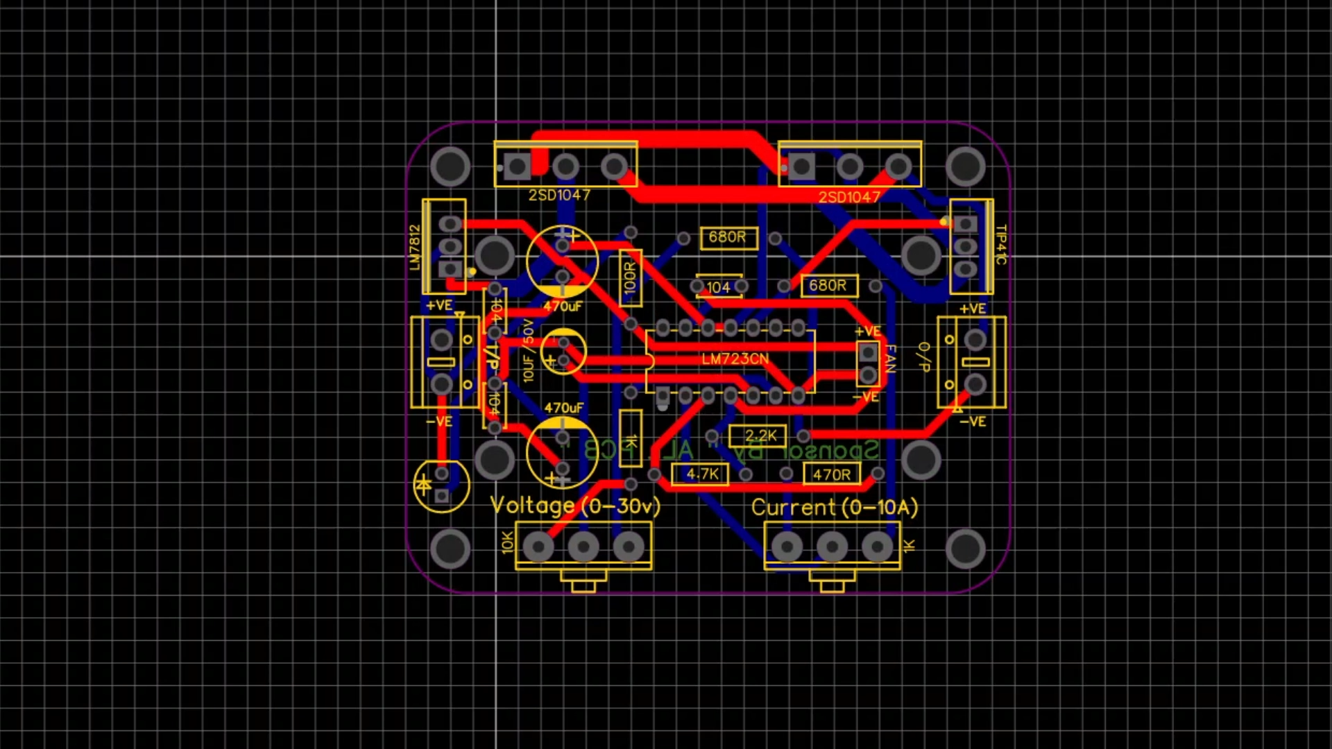
PCB DesigningWe have to design a PCB according to our requirements. We have manufactured our PCB from ALL PCB. ALL PCB is the world's fastest PCB manufacturing company.
As you can see the PCB which we are going to use for the Variable Power supply are manufactured from the ALL PCB, which are delivered within a week of placing the order and are of very good quality.
Ordering PCB from ALLPCBYou need to just upload your gerber file and select the color and quantity for your PCB, within a week your PCB will be delivered at your doorstep.
You can get your first PCB at a low price of 1$, if you place an order from the ALL-PCB. The manufacturer is committed to give the best of the service available in the market with minimal pricing.
Circuit Connection and SolderingThe circuit connection for the Variable Power Supply is given here. We have to solder all the components on PCB as per the circuit connection shown.
After placing all the components in their respective places we have to solder it properly.
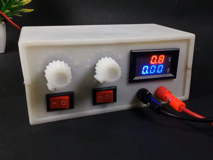
Now all the components are soldered on the PCB we are ready to place the PCB in a Case. We have designed this case using a 3D printer.
Now we have placed all the components inside the case we have built. After placing it in their desired places we close the cover. Now our Lab Bench Power Supply is ready for Testing.
TestingIn this Testing process we are going to test our Power Supply by using two loads, one is a DC Motor and another one is a DC Fan. These are the perfect load to check our Lab Bench Power Supply.
1. As you can see by rotating the voltage nub we are controlling the speed of the motor. Here we can give 0 to 30 v as per our requirement. As we start increasing the input voltage by rotating the nub the Motor speed keeps on rising.
2. And here we are going to use a Fan as our load to check the Lab Bench Power Supply. Here we can give 0 to 30 v as per our requirement. As we start increasing the input voltage by rotating the nub the Fan speed keeps on rising.
This is indeed a very useful project for those tech enthusiasts who love to play on electronics components. This will be a great power source for their device and a Secure one.


Comments