

Hardware components | ||||||
| × | 1 | ||||
| × | 1 | ||||
| × | 1 | ||||
| × | 2 | ||||
| × | 1 | ||||
| × | 2 | ||||
| × | 2 | ||||
| × | 2 | ||||
| × | 3 | ||||
| × | 2 | ||||
Software apps and online services | ||||||
| ||||||
| ||||||
Hand tools and fabrication machines | ||||||
 |
| |||||
 |
| |||||
 |
| |||||
This project is a scale for measuring filament weight whilst loaded on the printer which replaces the spool holder and allows visualisation of current weight and the weight as filament is used.
Wanting to know if there is sufficient filament on a spool for those long print jobs prior to printing, normally making use of a separate scale and a calculator.
But a more practical solution would be a scale integrated within the printer.
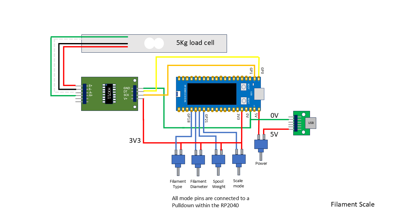
The scale uses a Beam load cell (5kg max), a HX711 ADC for signal conditioning and an RP2040 (Rapsberry Pi compatible microcontroller), with integrated LCD. Mounted on a custom made PCB and enclosed in a 3D printed case.
CircuitThe load cell is connected to channel A at the HX711 via four wires to E+ (red), E- (black), A-(white) & A+(green).
E+ (3V3), and E- (0V), are the load cell supply lines and A+ and A- (1kR output resistance), connect to the amplifier inputs.
B+ & B- the other channel is not connected.
The outputs from the HX711 are connected to the RP2040.
HX711 DT to RP2040 GP0
HX711 SCK to RP2040 GP1
HX711 V+ to RP2040 3V3
HX711 GND to 0V
The selection of the various options are accomplished using switches connected to GP18 to GP21.
These pins are internally connected to 0V via resistors (50kR to 80kR), within the RP2040.
The switches connecting GP18 to GP20 are Momentary switches.
These are used to select the filament options.
Filament Type: One pin connected to GP18 with the other connected to 3V3.
Filament Diameter: One pin connected to GP19 with the other connected to 3V3.
Spool: One pin connected to GP20 with the other connected to 3V3.
The Mode and Power switches can utilise toggle, push button or slide switches. Although I have used toggle switches.
Mode selection: One pin connected to GP21 with the other connected to 3V3.
The mode selection will determine whether entry/pause or measurement..
A power switch is included between the USB_C input (5V), and the RP2040 Pin40 (VBUS), there is an internal Schottky diode (Vf<0.3V@100mA), in series with this input which provides reverse polarity protection.
I prefer to isolate the supply via a switch for general use rather than connecting directly to the onboard USB and use the onboard USB for programming and testing.
PCBThe PCB is double sided and was designed using EagleCAD and manufactured at OSHpark.
Board Size: 49.5(D) x 78.74(W) mm with 3mm mounting holes in each of the 4 corners.
The RP2040 is mounted on the front and the HX711 is mounted behind it on the other side of the board.
Three switches control option changes, Filament Type, Filament Diameter & Spool Weight. Provision being made for through hole or surface mounted switches.
One SPDT switch to select the mode of operation.
One SPDT switch for power control.
Provision is made to attach a separate USB_C breakout board to the PCB or remote connected.
Additionally there is an auxillary supply input on 2 separate pins.
Subject to user preference the project can be mounted without an enclosure as the PCB accommodates low profile switches or using offboard switches using the supplied enclosure details.
3D PrintingThe elements were designed using BlocksCAD and TinkerCAD.
Filament: PLA (Black), simply to match with the printer but any colour as suits personal choice.
Layer Height: 0.1mm for the Scale_clamp and nut, 0.15mm for the Scale_load, Bracket and enclosure.
Infill: 100%
Bed Adhesion: Skirt
No supports
All parts are correctly orientated within the files for printing directly.
All parts where sliced using Cura 5.8.1 and printed on a Elegoo Neptune 4 Pro.
1: Scale_load. 45(dia) x 71(H) mm, Weight: 29g
2: Scale_clamp: 50(dia) x 60(H) mm, Weight: 28g
3: Nut: 41.2(dia) x 10(H) mm, Weight: 8g
4: Bracket. Size: 80(L) x 50(W) x 94(H) mm, Weight: 48g
5: Enclosure: Size: 72(W) x 83.5(L) x 35(H) mm, Weight: 38g
Scale Arm AssemblyOrientate the load cell with the end label facing the non flange end of the scale arm, such that the screw holes in the load cell and scale arm are aligned when the load cell is slid into place.
Fix the load cell in place with 2 x M4 x 17mm countersunk screws.
With the flanged end of the scale clamp orientated toward the non flange end of the scale arm push the wires of the load cell through the centre hole of the scale clamp with the screw holes aligned.
The inner part of the flange end of the scale clamp is stepped to allow the side of the load cell to which the wires emerge to not foul during insertion.
Fix the scale clamp to the load cell with 2 x M5 x 17mm countersunk screws.
There will exist a small gap between the scale arm and scale clamp allowing the scale arm to flex in relation to the scale clamp.
Solder a 4pin SIL socket on the ends with the wires in the following order E+(red), E-(black), A-(white), A+(green).
HX711 PCB preparationThe HX711 was purchased fully assembled on a PCB with additional conditioning components all that is required is to solder in place the SIL pins.
Orientate the HX711 PCB with the HX711 uppermost and with the six drill holes on the left.
Insert a 4pin right angle header with the short pins in the four holes starting top left (E+, E-, A-, A+) and solder in place.
Insert a 4pin straight header from the underside with the short pins uppermost and solder in place.
Slip a plastic washer over a M2 plastic pan head screw.
Pass the M2 screw through one of the mounting holes to the front of the HX711 PCB.
Fit a M2 nut over the M2 screw and tighten.
Repeat the process at the other mounting hole.
On each screw fit a M2 x 10mm threaded standoff.
Further details regarding the HX711 can be found in the attached datasheet.
Protective Clear WindowA clear window is used to add some protection in front of the RP2040 which is also flexible enough, to enable if necessary the pressing of the RESET button in the event that the microcontroller locks up.
This is made from a piece of a clear film (PET or similar), from a blister pack.
Cut a rectangle to the following size: 50(H) x 80(L) mm
Drop it into the back of the main cover and while holding it in place insert a marker into the screw holes at the front to mark the film.
With a 3mm drill bit, awl or punch, cut out the holes.
Main Unit AssemblyPosition and solder in the two 100nF capacitors.
From the underside insert a 4 pin SIL socket into the holes designated for the HX711 (JP3) and solder in place.
Insert and solder in 2 x 20pin SIL sockets.
Insert a M3 plastic screw from the top to the back of the main PCB and fit a plastic washer and a M3 x 10mm threaded standoff. This helps to retain the HX711 PCB in place once the main PCB is attached to the scale bracket.
Insert the 4pin header of the HX711 PCB into the 4pin socket at the back of the main PCB and secure in place with 2 x M2 x 4mm plastic screws.
USB BoardPower is provided by a separate USB board which is attached remote from the main PCB at the back of the bracket.
A series of holes are provided close to the corner of the bracket to fit the USB board.
Measure 2 x lengths of wire sufficient to reach the USB board and the power connections on the main PCB.
A straight pin SIL header was fitted to the USB board to facilitate wire wrapping although soldering either or without the header is possible.
The USB board is secured in place with 2 x M2 x 6mm self tapping screws.
Holes are provided in the Scale bracket to allow the wires to be threaded through to the main PCB which are connected to the 0V and 5V pins.
Main CoverThe main cover holds the switches that are used to control the scale and provide a degree of protection whilst allowing visibility of the screen.
Widen the five switch holes with a 6.5mm drill bit if necessary.
Starting at the left hand most hole fit 3 x push button switches.
In the remaining two holes fit the toggle switches.
Cut ten lengths of wire sufficient to allow easy soldering of the wires and to reach from the switches to the main PCB.
Attach a pair of wires at each switch adopting the same convention.
Attach a pair of wires from each switch to the main PCB at SW1(Filament), SW2(Diameter), SW3(Spool).
A pair of wires are attached at S1(Mode), and S5(Power).
There is also an opening on the right hand side coincident with the USB socket on the microcontroller.
This alows access as an alternative power source and software editing without having to open the main cover.
If not already done so, fit the RP2040.
Fit the protective film into the main cover, if necessary secure in place with a flexible adhesive.
Scale bracketTo the scale bracket secure 4 x 15 + 5mm plastic threaded standoffs (one in each corner), and a washer with nylon screws. Insert the screw through the corner hole in the rectangular section of the bracket followed by a washer and the standoff and repeat in the other corners.
Thread the leads from the Load cell with the attached 4pin SIL socket and pass it through the centre hole in the Scale bracket.
Ensure the load cell is orientated correcly with the arrow on the end of the load cell pointing downwards.
Secure the Scale arm in place with the large nut.
Pass the leads from the load cell through the centre hole in the Scale bracket and connect to the 4 SIL pins of the HX711 board.
Seat the main PCB on the threaded ends of the standoffs, secure the PCB in place with 4 x 15mm plastic threaded standoffs.
Fit the main cover with the 4 corner holes aligned with the standoff holes.
Secure the main cover at the front via the corners with 4 x M3 x 5mm plastic screws.
Final AssemblyRemove the existing spool holder.
Pass the threaded end of the encapsulated load cell through the hole in the bracket and through the spool arm secure with the nut.
Feed the 4 pin SIL socket through the smaller hole in the bracket and attach to the HX711 board.
Fit the front of the case with 4 x M4 x 6mm nylon screws.
SoftwareThe software is written in MicroPython v1.15 using Thonny 3.3.13
The firmware library used was rp2-pico-20210418-v1.15.uf2 this and/or an updated version can be downloaded from the Waveshare site under Software Setup which also includes installion details if required.
Once the firmwave is installed and a connection is established to enable programming.
Rename library hx711f.py (load cell), to hx711.py and copy to the RP2040
Copy library LCD096.py (display), to the RP2040
Copy the three text files ftypes.txt, spool.txt and fdia.txt to the RP2040.
How does this information enable the filment weight and length to be found.
Filament weight = Total Weight (spool + Filament) - Spool Weight [Spool Weight contained within spool.txt]
Volume(cm3) = Filament Weight(g)/Filament Density(g/cm3) [Filament Density contained within ftypes.txt]
Filament Length(m) = Filament Volume/(((Filament Diameter/2)^2)*PI [Filament Diameter within fdia.txt]
The text files contain custom configuration information enabling the user to simply edit the files without requiring modification to the code.
ftypes.txt contains a list of filament types and density(kg/m3).
A link is provided to a source of filament types and densities other lists are available*.
spool.txt contains a list of spools from different manufacturers and their weight(g).
A link is provided to a source of empty spool weights there are other lists and if in doubt weigh your empty spools*
*No affilation to these links feel free to use other sources.
fdia.txt contains a list of filament diameters(mm).
The same information within these files is also coded within the software as three separate lists.
This means that the user has the option to either use the coded defaults or the contents of the files.
Subject to user preference the lists and/or files can be edited as required.
How is this accomplished.
When the software loads it checks whether each text file is usable, if the file is usable the software loads the data within the file. If the text file is not usable then the software loads the coded defaults.
Any modifications to the text files must follow the same format found within the original file to ensure compatibility.
I created the files with Notepad loaded these into Thonny and saved them to the RP2040.
Run the calibration process and edit the calibration factor in Filament_Scale6.py before renaming and copying.
Rename Filament_Scale6.py to main.py and copy to the RP2040.
CalibrationPrior to operation the scale will require calibration.
Ideally the calibration and operational environmental conditions should be the same for consistency as variations in temperature and humidity will impact the results.
Switch the scale on and allow to stabllise under the environmental conditions prior to calibration.
Rather than manually entering values to hopefully identify the calibration factor which would be somewhat a coarse value I decided it would be better to automate the process.
This would simplify, speed up and improve the accuracy compared to a manual process.
Obtain a known weight and/or verify with another scale and record the weight, this will be the reference weight.
Open Calscale.py
Changed the numeric value on the following line to the value of the reference weight.
calfac, NetWeight = bsa(812) in this case the weight is 812g.
The third value in the following line is the calibration factor which is a starting point for the calibration reference search.
hx = HX711(dout, dpclk, 405) in this case 405 is the calibration factor. (This is the actual value for the load cell I used)
If the load cell is changed at a later stage calibration will need to be rerun.
Run Calscale.py
The LCD will display the following: "Remove weight now!" with a 10 second countdown.
This gives time to remove the spool from the spool arm, if one is in place.
Following this the LCD will display "Initializing", during this period the Tare (unladen weight), will be captured.
If the HX711 fails to initialize the following will be displayed "HX711 failed", in red.
If there are no issues.
The following will be displayed "Set D to Weigh".
Place a know weight onto the scale.
Set the D switch into the Weigh position.
The display will show "Calibrating"
This process will take a few seconds to complete.
During the calibration process a binary successive approximation search is carried out.
The search adjusts the calibration factor and carries out the following calculation:
Weight(mid) = (Mean Measurement - Tare) / calibration factor
Then compares the weight(mid), to the reference weight (target) and if the weight(mid), is within the tolerance (0.5) the search is terminated.
Once calibration is completed the display will show "Calibrated" the corrected weight and the new calibration factor.
The initial weight, corrected weight and new calibration factor are also shown on the Shell.
Open Filament_Scale6.py (main.py)
Replace the third value in the following line hx = HX711(dout, dpclk, 405), with the new calibration factor.
Save the changes to Filament_Scale6.py (main.py)
Its always a good idea to check the calibration at regular intervals in case the scale has drifted, this can be verified with a reference weight.
OperationApply power to the Scale.
The LCD will display the following: "Remove weight now!" with a 10 second countdown.
This gives time to remove the spool from the spool arm, if one is in place.
Following this the LCD will display "Initializing", during this period the Tare (unladen weight), will be captured.
If the HX711 fails to initialize the following will be displayed "HX711 failed", in red.
If there are no issues.
The display will next show the mode menu:
A:Filament Scale (First on the left)*
B:Standard Scale (Second on the left)*
- FIve switches on the front panel referenced A to E.
Press the button for the required Scale option.
A: Filament ScaleSwitch D must be set to entry/pause mode to update the menu.
Three input fields will be displayed on the LCD.
Filament Type, Filament Diameter & Spool.
Each field controlled by a separate button.
E.g
Filament Type= PLA (Switch A)
Filament Diameter= 1.75mm (Switch B)
Spool= eSUN/244g (Switch C)
Repeatedly press the appropriate button to cycle through its option list.
Following selection of the required fields the following will be displayed "Set D to Weigh" in yellow.
Set the D switch into the Weigh position.
This will display the length of filament in metres and the weight in grammes.
B: Standard Scale.Two modes are applicable.
1: With the D switch in the Weigh position.
The display will show only the live weight in grammes.
2: With the D switch in the entry/pause position.
The display will show "Standard Scale" and "Set D to Weigh"
The current weight will be held on the display.
Set the D switch into the Weigh position to return to live measurement.
In either Scale mode.
Measurement can be held displaying the length and/or weight at that instant by setting of the D switch to entry/pause.
Set the D switch to Weigh to return to live measurement.
Power cycle or press the Reset button to return to the main option menu.
For any additional information not contained here see:
Filament Scale : 15 Steps (with Pictures) - Instructables
May prove more cost effective to buy a range of values rather than individual values unless you already have them available. Some components may also have a MOL greater than the quantity specified in the component list.
No affiliation to any of the suppliers, feel free to obtain the supplies from your preferred supplier if applicatble.
Links valid at the time of publication.
This project has now been published Jan 2026 in Issue 161 of the Offical Raspberry Pi Magazine.


Comments