


Hardware components | ||||||
 |
| × | 1 | |||
 |
| × | 1 | |||
 |
| × | 1 | |||
 |
| × | 1 | |||
Software apps and online services | ||||||
 |
| |||||
 |
| |||||
In everyday facilities like server rooms, medicine storage units, and greenhouses, managers must keep close track of environmental conditions. A server room that overheats can cause equipment to shut down abruptly. A medicine cabinet that drops below freezing can ruin insulin and vaccines. To prevent these problems, facilities use monitoring boxes that track temperature, humidity, light, and movement, sounding an alarm the moment conditions become unsafe.
This project implements an environmental room monitor on an ESP32 microcontroller using native ESP-IDF C/C++ and FreeRTOS. The system measures room conditions, displays readings on an OLED screen navigated with a rotary knob, sounds a 2000 Hz hardware buzzer alarm if temperature thresholds are breached, and turns off the display after 15 seconds of quiet to save energy.
MotivationMost beginner tutorials build microcontroller projects inside a single loop (often called a super-loop or while(1) loop). In that structure, the processor handles one job after another in a straight line: read a sensor, wait, update a screen, wait, and check an alarm.
This simple loop breaks down when you connect sensors with slow communication protocols:
- Reading a digital DHT22 sensor requires the processor to time electrical pulses for up to 25 milliseconds.
- Refreshing an SSD1306 OLED screen over an I2C bus takes another 10 to 15 milliseconds.
- Standard
delay()calls cause timing drift because the delay only starts after the sensor reading finishes.
If a user turns a knob or walks past a motion sensor while the processor is busy waiting inside one of these routines, the processor is frozen and misses the electrical signal completely. The device feels laggy and unresponsive.
To solve this, this project divides the program into six independent FreeRTOS tasks. A real-time scheduler gives CPU time to whichever task has the most urgent work, pausing slower background routines whenever user input or motion occurs.
Features- Six independent FreeRTOS tasks scheduled preemptively based on urgency so user inputs and alarms are never delayed.
- Drift-free periodic sampling using
vTaskDelayUntil()to keep sensor readings strictly on schedule every 2.0 seconds. - Safe inter-task communication using typed FreeRTOS queues rather than unprotected global variables.
- Clean serial diagnostics protected by a FreeRTOS mutex (
serialMutex) so printed messages never scramble together. - State signaling using an event group (
systemEvents) for motion detection and screen timeout flags. - Four-page screen navigation using a physical rotary encoder knob with continuous wraparound in both directions.
- Audible 2000 Hz temperature alarm using the ESP32 hardware PWM timer when temperature drops below 18.0 °C or rises above 30.0 °C.
- Power-saving state machine that blanks the OLED screen after 15.0 seconds without motion and wakes up instantly when movement returns.
- 13 automated unit tests executed using Unity on a host PC (
nativeenvironment) to verify alarm math, navigation logic, and state transitions.
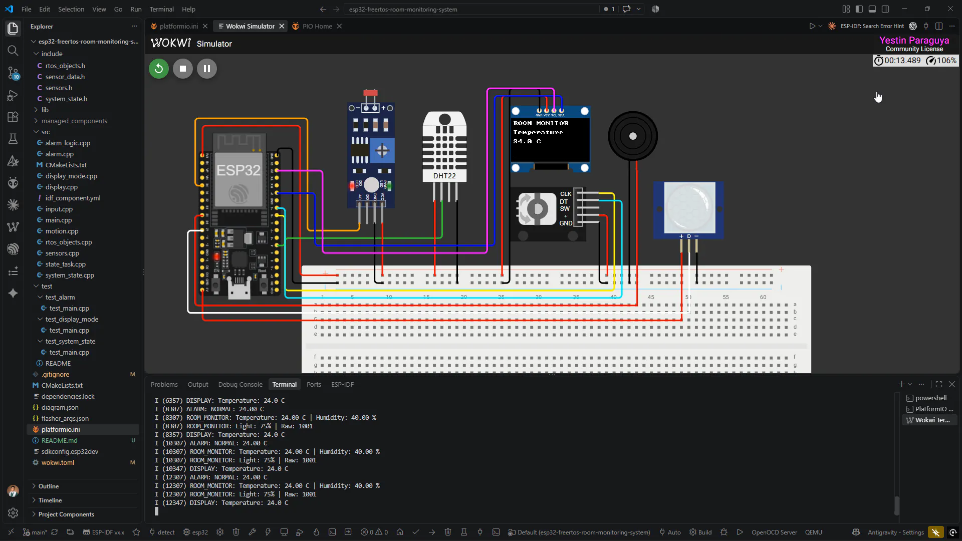
The system uses components that can be assembled on a physical breadboard or simulated inside Wokwi:
All sensors and modules share a common ground (GND) and run from the ESP32 3.3V power pin:
ESP32 Wiring Connections:
- GPIO 4  <--> DHT22 Data Pin (1-Wire digital protocol)
- GPIO 34 <--> Photoresistor Voltage Divider (ADC1 Channel 6)
- GPIO 21 <--> SSD1306 OLED SDA (I2C serial data line)
- GPIO 22 <--> SSD1306 OLED SCL (I2C serial clock line)
- GPIO 18 <--> KY-040 Rotary Encoder CLK (Clock interrupt line)
- GPIO 19 <--> KY-040 Rotary Encoder DT (Direction line)
- GPIO 25 <--> Piezo Buzzer Positive Leg (LEDC PWM output)
- GPIO 27 <--> PIR Motion Sensor Output (Active high digital input)
Figure 1: Wokwi circuit schematic and hardware breadboard wiring.
System architectureGood embedded architecture separates physical hardware drivers, operating system communication tools, and calculation logic into distinct layers. This structure keeps code maintainable and allows calculation rules to be tested on a computer without physical hardware.
The project is structured into three layers:
- Hardware Driver Layer (
sensors.cpp,display.cpp,input.cpp,motion.cpp,alarm.cpp): Interacts directly with ESP-IDF hardware drivers for GPIO pins, ADC1, I2C, and PWM. - FreeRTOS Synchronization Layer (
rtos_objects.cpp,main.cpp): Creates and manages queues, mutexes, event groups, and task lifecycles. - Pure Decision Logic Layer (
alarm_logic.cpp,display_mode.cpp,system_state.cpp): Contains pure calculation functions that do not depend on hardware headers, making them fully testable in automated unit test suites.
Figure 2: Three-layer system architecture showing physical sensors, ESP-IDF drivers, and FreeRTOS tasks with IPC queues. To see high quality pic of this click this link: https://drive.google.com/file/d/1JpRkVCIPa_DLTmbtlFnCvmmIpGJ7R82e/view?usp=sharing
FreeRTOS architectureThe system divides responsibilities across six tasks:
Explanation for readers: In FreeRTOS, higher numbers mean higher priority. The processor will always run the ready task with the highest priority number. Priorities are established based on task urgency and execution duration:
- Priority 3 (Highest:
InputTaskandMotionTask): User knob clicks and motion pulses are brief (lasting only a few milliseconds). If the processor does not handle them immediately, the signals pass and the user feels a missed click. Because these tasks take less than 0.1 milliseconds to process, giving them Priority 3 ensures immediate response without delaying other tasks. - Priority 2 (Medium:
AlarmTaskandStateTask): Evaluating temperature limits and checking the 15-second inactivity timeout are system safety jobs. They take less than 0.5 milliseconds to run, execute quickly, and yield CPU time. - Priority 1 (Lowest:
SensorTaskandDisplayTask): Updating the OLED display over I2C takes 10 to 15 milliseconds, and reading the DHT22 takes 25 milliseconds. IfDisplayTaskwere high priority, that 15-millisecond screen update would lock out the encoder knob and miss user clicks. SettingDisplayTaskto Priority 1 lets knob turns interrupt screen drawing at any moment.
Figure 3: FreeRTOS task communication and event sequence, and you can get to see the full high quality photo of this in this link : https://drive.google.com/file/d/1TXiK6Ms9ed_1bkWDaEBp8ZTVSDq36Fpl/view?usp=sharing
How it worksDrift-free periodic samplingInstead of using vTaskDelay(), which pauses relative to when the call is reached and causes timing drift, SensorTask uses vTaskDelayUntil(). This function computes absolute tick targets based on the previous wake-up timestamp. Even if reading the DHT22 takes 10 milliseconds on one cycle and 25 milliseconds on the next, SensorTask always wakes up at exact 2.0-second intervals.
sensorQueue(capacity 5): Transmits full sensor readings fromSensorTasktoDisplayTask.alarmQueue(capacity 1): Sends the newest temperature toAlarmTaskusingxQueueOverwrite(). If the alarm task is briefly busy, it only needs the freshest value to decide if the buzzer should sound right now.displayModeQueue(capacity 1): Sends active page updates fromInputTasktoDisplayTask.encoderQueue(capacity 16): Carries turn directions from the interrupt routine toInputTask.
systemEvents holds two bit flags:
BIT0 (EVENT_MOTION): Set to 1 when the PIR sensor senses movement and 0 when movement stops.BIT1 (EVENT_INACTIVE): Set to 1 byStateTaskwhen 15 seconds pass without motion, telling the display to blank itself.
All tasks share one UART serial port. SensorTask, AlarmTask, and StateTask take serialMutex before printing and release it after finishing, preventing printed lines from interleaving and scrambling on the terminal.
The system operates in two states:
- ACTIVE: The OLED screen is illuminated, telemetry updates every 2 seconds, and the rotary encoder switches between screens.
- INACTIVE: When 15.0 seconds pass without motion, the system switches to INACTIVE and blanks the OLED screen to conserve power and protect hardware. As soon as someone walks past the PIR sensor, the system switches back to ACTIVE and the screen lights up immediately.
Figure 4: Energy management state machine transition diagram.
Testing and verificationAutomated host unit tests (13 passing)Pure calculation logic was evaluated on the development computer using Unity in PlatformIO:
pio test -e nativeFigure 6: Automated Unity host unit test suite passing all 13 test cases in the native environment.
Results:
test_alarm(5 tests): Confirmed that 17.9 °C triggers a low alarm, 18.0 °C is normal, 24.0 °C is normal, 30.0 °C is normal, and 30.1 °C triggers a high alarm.test_display_mode(4 tests): Verified clockwise navigation (Temp -> Humidity -> Light -> Motion -> Temp) and counterclockwise navigation in reverse with wraparound in both directions.test_system_state(4 tests): Verified system stays active at 14.99 seconds, enters inactive at 15.00 seconds, stays inactive after 15.00 seconds, and motion overrides the timeout.
All ten requirements were verified in the Wokwi simulator:
- Temperature and humidity sliders update on the OLED screen within 2 seconds (FT-01, FT-02).
- Photoresistor slider maps raw ADC numbers to a 0% to 100% light scale (FT-03).
- Rotary knob cycles pages forward and backward cleanly (FT-04, FT-05).
- Buzzer sounds a 2000 Hz tone when temperature drops below 18 °C or rises above 30 °C, silences at 21.4 °C (FT-06, FT-07).
- System stays active with motion, blanks the screen at 14.98 seconds of quiet, and wakes up immediately on new motion (FT-08, FT-09, FT-10).
- CPU starvation: Removing
vTaskDelayUntil()instateTaskcaused it to consume 100% of Core 0, starving the Idle Task and triggering an ESP-IDF Task Watchdog Timer crash at 5.2 seconds. This proves that every task in a preemptive system must block or yield. - Priority skew: Raising
stateTaskto Priority 5 did not starve other tasks because it executed in under 0.2 ms and slept for 50 ms, showing that blocking duration matters as much as priority. - Mutex removal: Removing
serialMutexcaused rapid encoder turns and temperature alarms to collide, producing scrambled characters on the serial line.
The system runs continuously in Wokwi, logging clear telemetry to the serial console and presenting one measurement page at a time on the OLED screen.
Figure 5: Live operational demonstration showing active OLED display page, sensor readings, and real-time FreeRTOS logging. Watch the full 3-minute video on YouTube.
Challenges encountered- Flash size configuration: PlatformIO defaulted to a 2MB flash setting while the simulated ESP32 board contained 4MB. This was resolved by updating
CONFIG_ESPTOOLPY_FLASHSIZE="4MB"insdkconfig.esp32devandflasher_args.json. - Deprecated LEDC interrupt flag: The compiler flagged
channelConfig.intr_type = LEDC_INTR_DISABLEas deprecated in newer ESP-IDF versions. Removing the line fixed the warning because the driver disables interrupts by default.
- Decoupling decision logic from hardware drivers makes firmware testable on a computer using automated unit tests.
- In a priority-based preemptive operating system, every task loop must contain an explicit blocking call to give lower-priority tasks CPU time.
- Mutexes are necessary when multiple independent tasks share a single physical communication channel like a UART port.
- Simulation differences: In Wokwi, electrical signals are clean and square. In real life, mechanical rotary knobs have switch contact bounce that requires hardware filter capacitors or a software debounce timer, and physical DHT22 sensors take several seconds to adjust to temperature changes.
- ADC non-linearity: The ESP32 analog converter is non-linear near 0V and 3.3V, which requires reading factory calibration values from eFuse memory in physical builds.
- Store user alarm limits in non-volatile storage (NVS flash memory) so settings stay saved when the device is unplugged.
- Transmit telemetry data over Wi-Fi to a cloud dashboard using the MQTT protocol.
- Use the ESP32 Ultra-Low-Power (ULP) co-processor to monitor motion and light while the main CPU cores sleep.
The complete source code, schematics, test suites, and documentation are available at:https://github.com/xavieryyyyyy/esp32-freertos-room-monitoring-system
References- Course: BCA152 Microcontrollers, Mindanao State University - Iligan Institute of Technology (MSU-IIT), College of Computer Studies.
- Instructor: Asst. Prof. Paul Rodolf P. Castor, M.Sc.
- Framework: Espressif IoT Development Framework (ESP-IDF) and FreeRTOS.
- Simulator: Wokwi Embedded Systems Simulator.


Comments