


Learning, experimentation, creating. The thing that drives most of us in this realm. After assembling and completing a project that someone else has put together for you, the next step is to expand on it and make it yours. This was a fun and challenging project as it put all my skills to work.
Who doesn't need a digital bubble level that has both one and two axis.. So I set out on the net to find an example and thats when I discovered DroneBotWorkShop's example for a 1 axis digital level. I created the project from their instructions and then got to work modifying it to handle another axis and drive the 8x8 LED Matrix.
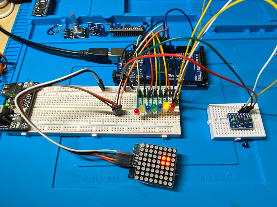
When level on both axis, the outer border lights up and LED intensity goes to max.
Parts:
- Arduino Mega
- 7x 220 Resistors
- 7x LEDs (2 Red, 2 Yellow, 2 Blue, 1 Green)
- Elegoo MAX7219-DotMatric-Module-V02
- MPU6050 (GY-521) Gyro/Accel
- Breadboard & 5V PSU
- Various lengths of wire
Wiring Diagram:
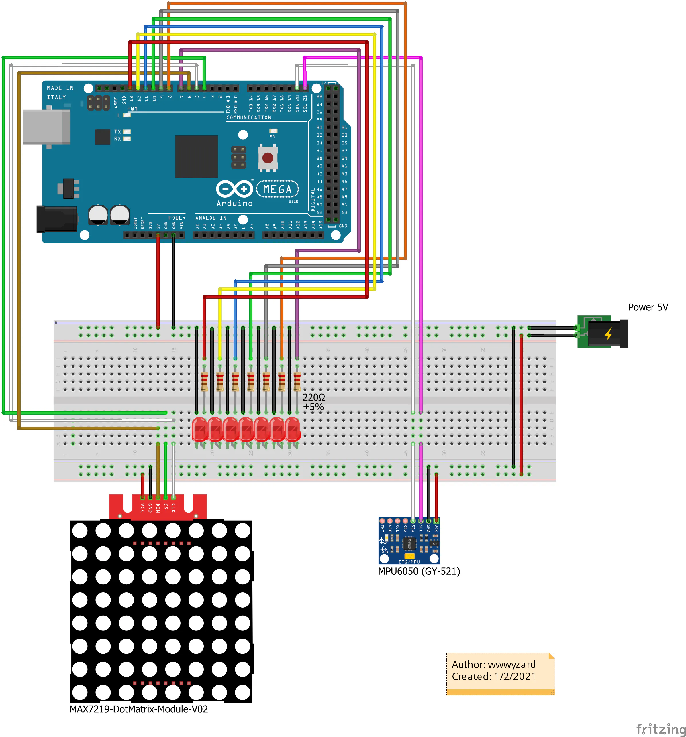
// Include Wire Library for I2C
#include <Wire.h>

// Include for 8X8 Dot Matrix
#include "LedControl.h"
LedControl lc = LedControl (6, 5, 4, 1);

//Tolerance
// 0-10 = Ultra Fast - Loose accuracy but averages ok
// 11-100 is more acurrate but slower as you scale up.
const int tolerance = 10;

//Precision
const float Low4 = -1.00;
const float Low3 = -0.75;
const float Low2 = -0.50;
const float Low1 = -0.25;
const float High1 = 0.25;
const float High2 = 0.50;
const float High3 = 0.75;
const float High4 = 01.00;

// BreadBoard LED Pins
int led0 = 7;
int led1 = 8;
int led2 = 9;
int led3 = 10;
int led4 = 11;
int led5 = 12;
int led6 = 13;

// Vars for positioning later
int row;
int col;

// Display counter
int displaycount = 0;

//Variables for Gyroscope
int gyro_x, gyro_y, gyro_z;
long gyro_x_cal, gyro_y_cal, gyro_z_cal;
boolean set_gyro_angles;

long acc_x, acc_y, acc_z, acc_total_vector;
float angle_roll_acc, angle_pitch_acc;

float angle_pitch, angle_roll;
int angle_pitch_buffer, angle_roll_buffer;
float angle_pitch_output, angle_roll_output;

// Setup temp variable
int temp;

void setup() {

  // the MAX72XX is in power-saving mode on startup,
  // we have to do a wakeup call
  lc.shutdown (0, false);

  //Start I2C
  Wire.begin();

  // Set Board LEDs as outputs
  pinMode(led0, OUTPUT);
  pinMode(led1, OUTPUT);
  pinMode(led2, OUTPUT);
  pinMode(led3, OUTPUT);
  pinMode(led4, OUTPUT);
  pinMode(led5, OUTPUT);
  pinMode(led6, OUTPUT);

  //Setup the registers of the MPU-6050
  setup_mpu_6050_registers();

  //Read the raw acc and gyro data from the MPU-6050 1000 times
  for (int cal_int = 0; cal_int < 1000 ; cal_int ++) {
    read_mpu_6050_data();
    //Add the gyro x offset to the gyro_x_cal variable
    gyro_x_cal += gyro_x;
    //Add the gyro y offset to the gyro_y_cal variable
    gyro_y_cal += gyro_y;
    //Add the gyro z offset to the gyro_z_cal variable
    gyro_z_cal += gyro_z;
    //Delay 3us to have 250Hz for-loop
    delay(3);
  }

  // Divide all results by 1000 to get average offset
  gyro_x_cal /= 1000;
  gyro_y_cal /= 1000;
  gyro_z_cal /= 1000;

  // Start Serial Monitor
  Serial.begin(115200);

}

void loop() {

  // Get data from MPU-6050
  read_mpu_6050_data();

  //Subtract the offset values from the raw gyro values
  gyro_x -= gyro_x_cal;
  gyro_y -= gyro_y_cal;
  gyro_z -= gyro_z_cal;

  //Gyro angle calculations . Note 0.0000611 = 1 / (250Hz x 65.5)

  //Calculate the traveled pitch angle and add this to the angle_pitch variable
  angle_pitch += gyro_x * 0.0000611;
  //Calculate the traveled roll angle and add this to the angle_roll variable
  //0.000001066 = 0.0000611 * (3.142(PI) / 180degr) The Arduino sin function is in radians
  angle_roll += gyro_y * 0.0000611;

  //If the IMU has yawed transfer the roll angle to the pitch angle
  angle_pitch += angle_roll * sin(gyro_z * 0.000001066);
  //If the IMU has yawed transfer the pitch angle to the roll angle
  angle_roll -= angle_pitch * sin(gyro_z * 0.000001066);

  //Accelerometer angle calculations

  //Calculate the total accelerometer vector
  acc_total_vector = sqrt((acc_x * acc_x) + (acc_y * acc_y) + (acc_z * acc_z));

  //57.296 = 1 / (3.142 / 180) The Arduino asin function is in radians
  //Calculate the pitch angle
  angle_pitch_acc = asin((float)acc_y / acc_total_vector) * 57.296;
  //Calculate the roll angle
  angle_roll_acc = asin((float)acc_x / acc_total_vector) * -57.296;

  //Accelerometer calibration value for pitch
  angle_pitch_acc -= 0.0;
  //Accelerometer calibration value for roll
  angle_roll_acc -= 0.0;

  if (set_gyro_angles) {

    //If the IMU has been running
    //Correct the drift of the gyro pitch angle with the accelerometer pitch angle
    angle_pitch = angle_pitch * 0.9996 + angle_pitch_acc * 0.0004;
    //Correct the drift of the gyro roll angle with the accelerometer roll angle
    angle_roll = angle_roll * 0.9996 + angle_roll_acc * 0.0004;
  }
  else {
    //IMU has just started
    //Set the gyro pitch angle equal to the accelerometer pitch angle
    angle_pitch = angle_pitch_acc;
    //Set the gyro roll angle equal to the accelerometer roll angle
    angle_roll = angle_roll_acc;
    //Set the IMU started flag
    set_gyro_angles = true;
  }

  //To dampen the pitch and roll angles a complementary filter is used
  //Take 90% of the output pitch value and add 10% of the raw pitch value
  angle_pitch_output = angle_pitch_output * 0.9 + angle_pitch * 0.1;
  //Take 90% of the output roll value and add 10% of the raw roll value
  angle_roll_output = angle_roll_output * 0.9 + angle_roll * 0.1;
  //Wait until the loop_timer reaches 4000us (250Hz) before starting the next loop

  // Increment the display counter
  displaycount = displaycount + 1;

  if (displaycount > tolerance) {

    // Print to Serial Monitor
    Serial.print(" | Pitch: "); Serial.println(angle_pitch_output);
    Serial.print(" | Roll: "); Serial.println(angle_roll_output);

    // clear the 8X8 display
    lc.clearDisplay (0);

    // Get position for BoardLEDs and Matrix Row
    // boardLights: 1 = On, 0 = Off,
    if (angle_pitch_output < Low4) {
      boardLights(1, 0, 0, 0, 0, 0, 0);
      row = 6;
    } else if ((angle_pitch_output > Low3) && (angle_pitch_output < Low2)) {
      boardLights(0, 1, 0, 0, 0, 0, 0);
      row = 5;
    } else if ((angle_pitch_output > Low2) && (angle_pitch_output < Low1)) {
      boardLights(0, 0, 1, 0, 0, 0, 0);
      row = 4;
    } else if ((angle_pitch_output > Low1) && (angle_pitch_output < High1)) {
      boardLights(0, 0, 0, 1, 0, 0, 0);
      row = 3;
    } else if ((angle_pitch_output > High1) && (angle_pitch_output < High2)) {
      boardLights(0, 0, 0, 0, 1, 0, 0);
      row = 2;
    } else if ((angle_pitch_output > High2) && (angle_pitch_output < High3)) {
      boardLights(0, 0, 0, 0, 0, 1, 0);
      row = 1;
    } else if (angle_pitch_output > High4) {
      boardLights(0, 0, 0, 0, 0, 0, 1);
      row = 0;
    }

    //Get Col Position
    if (angle_roll_output < Low4) {
      col = 0;
    } else if ((angle_roll_output > Low3) && (angle_roll_output < Low2)) {
      col = 1;
    } else if ((angle_roll_output > Low2) && (angle_roll_output < Low1)) {
      col = 2;
    } else if ((angle_roll_output > Low1) && (angle_roll_output < High1)) {
      col = 3;
    } else if ((angle_roll_output > High1) && (angle_roll_output < High2)) {
      col = 4;
    } else if ((angle_roll_output > High2) && (angle_roll_output < High3)) {
      col = 5;
    } else if (angle_roll_output > High4) {
      col = 6;
    }

    // set the brightness to a medium values
    lc.setIntensity (0, 8);

    //Light Up the 4 LED quadrant of the position of row & col (x & y axis)
    lc.setLed (0, col, row, true);
    lc.setLed (0, col + 1, row, true);
    lc.setLed (0, col, row + 1, true);
    lc.setLed (0, col + 1, row + 1, true);

    if ((row == 3) && (col == 3)) {
      lc.setIntensity (0, 16);
      lc.setRow (0, 0, B11111111);
      for (int i = 1; i < 7; i++) {
        lc.setRow (0, i, B10000001);
      }
      lc.setRow (0, 7, B11111111);
    } else {
      lc.setIntensity (0, 8);
      lc.setRow (0, 3, B00011000);
      lc.setRow (0, 4, B00011000);
    }
    displaycount = 0;
  }
}

void boardLights(int pos0, int pos1, int pos2, int pos3, int pos4, int pos5, int pos6) {
  digitalWrite(led0, pos0);
  digitalWrite(led1, pos1);
  digitalWrite(led2, pos2);
  digitalWrite(led3, pos3);
  digitalWrite(led4, pos4);
  digitalWrite(led5, pos5);
  digitalWrite(led6, pos6);
}

void setup_mpu_6050_registers() {

  //Activate the MPU-6050

  //Start communicating with the MPU-6050
  Wire.beginTransmission(0x68);
  //Send the requested starting register
  Wire.write(0x6B);
  //Set the requested starting register
  Wire.write(0x00);
  //End the transmission
  Wire.endTransmission();

  //Configure the accelerometer (+/-8g)

  //Start communicating with the MPU-6050
  Wire.beginTransmission(0x68);
  //Send the requested starting register
  Wire.write(0x1C);
  //Set the requested starting register
  Wire.write(0x10);
  //End the transmission
  Wire.endTransmission();

  //Configure the gyro (500dps full scale)

  //Start communicating with the MPU-6050
  Wire.beginTransmission(0x68);
  //Send the requested starting register
  Wire.write(0x1B);
  //Set the requested starting register
  Wire.write(0x08);
  //End the transmission
  Wire.endTransmission();

}

void read_mpu_6050_data() {

  //Read the raw gyro and accelerometer data

  //Start communicating with the MPU-6050
  Wire.beginTransmission(0x68);
  //Send the requested starting register
  Wire.write(0x3B);
  //End the transmission
  Wire.endTransmission();
  //Request 14 bytes from the MPU-6050
  Wire.requestFrom(0x68, 14);
  //Wait until all the bytes are received
  while (Wire.available() < 14);

  //Following statements left shift 8 bits, then bitwise OR.
  //Turns two 8-bit values into one 16-bit value
  acc_x = Wire.read() << 8 | Wire.read();
  acc_y = Wire.read() << 8 | Wire.read();
  acc_z = Wire.read() << 8 | Wire.read();
  temp = Wire.read() << 8 | Wire.read();
  gyro_x = Wire.read() << 8 | Wire.read();
  gyro_y = Wire.read() << 8 | Wire.read();
  gyro_z = Wire.read() << 8 | Wire.read();
}
Comments