

Hardware components | ||||||
_ztBMuBhMHo.jpg?auto=compress%2Cformat&w=48&h=48&fit=fill&bg=ffffff) |
| × | 1 | |||
 |
| × | 1 | |||
 |
| × | 1 | |||
| × | 1 | ||||
 |
| × | 1 | |||
 |
| × | 1 | |||
| × | 1 | ||||
Software apps and online services | ||||||
 |
| |||||
Since last time I have made a few changes. I have brought up my domain finally and will be adding weather calculations, updates, and other goodies. You can find it at https://www.wrightmac.net.
The code is up to version 0.7 and includes the SD card reader used in this update. If you want to build one yourself, check it out at Tindie.com. Yesterday I pulled out a SD card reader I had in my Arduino collection. It was really one of the easier parts of this build to date. I removed all of the wires from the Uno, mounted up the SD card shield (it is labeled that is uses Pin4, note made), re-wired all of the sensors, stuck in a card, and fired up an example sketch with the SD.h library. Here is a link to a good SD reference. I am not doing anything fancy, I just want some simple data logging for right now. And boy did this hit the spot.
I did one last test indoors before I set out for the FREEZING night tonight. It is a good night to stress test the gear. The data sheets say the pieces and parts are good the range. The enclosure is what it is as I only need it for testing right now. I am in the processing of reclaiming the shell of an old access point to use as one.
The next morning, today, I went out and it was still running! Now, did it bother to record anything.
And I am happy to report, why yes it did. I had it taking readings once a minute and now have something to start to shift through and see how I want to use it. Not to mention work on finishing the enclosure for it.
01 Dec Update:I have updated my code located in my GitHub repository. Cleaned up and working properly.
UPDATE:I recently got in the BMP280 I ordered a ways back. I took a little research and fiddling (I think I need to put my notes to their own project page), but I got it up and running. It is only outputting to the serial monitor right now. This is a late night update. Code for the LCD layout and combining sensors will come later this week.
Installation was straight forward.
- Vcc -> 3.3v
- And -> Gnd
- SDA -> pin4
- SCL -> pin5
There is also a pull-resistor, 4.7k on the SDO pin on the breakout board. With SDO pulled to Gnd the I2C address is 0x76, if to Vcc then the address is 0x77. If the SDO is left untouched the address is undefined and the device won't be found.
I have been finding the I2C scanner from the Arduino IDE a quite useful tool going down the I2C road. I used the BME280 library written by Tyler Glenn. You can find it linked here.
Stay tuned, I will be back with further updates, mostly with code next round.
A noob here to the Arduino world. I lurked on sites such as this and lackaday for quite a while. Then I bit the bullet and bought a box of cheap parts from China, waited and waited, and then let the micro controller fun begin!
I put various parts on a breadboard and got them to work. One sensor here or a couple of LEDs there is cool to start with but isn't too much fun. Not that this isn't a crucial step when learning, need to learn it one piece at a time. I saw quite a few weather stations out there. I like to dabble in the weather and my son was interested in making a weather station. So here is the project. It is just starting out; as with most projects scope creep has entered already.
- Phase 1 - get a basic setup of the DHT22 sensor, RTC, and LCD 5110
- Phase 2 - additional sensor for barometric pressure.
- Phase 3 add an ESP2866 for wireless transmission of the data. I will also turn Phase 1 project into the indoor weather station/test board.
- Phase Scope Creep - see the list at the end
After reading through a bunch of project pages, I dug through my inventory and pulled out an Arduino Uno clone, DHT22, RTC (DS3231), and a LCD 5110.
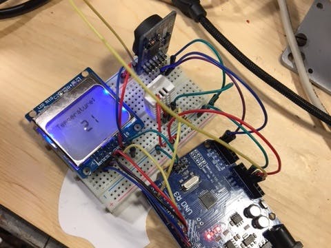
To get things started I just wanted to make sure both the LCD 5110 and DHT22 were working ok. I wired them on my trusted breadboard. It was pretty much straight forward. I am having issues with the DHT22 as at times it will not show up on the pin as expected. Removing the pull-up resistor is what got it working for me.
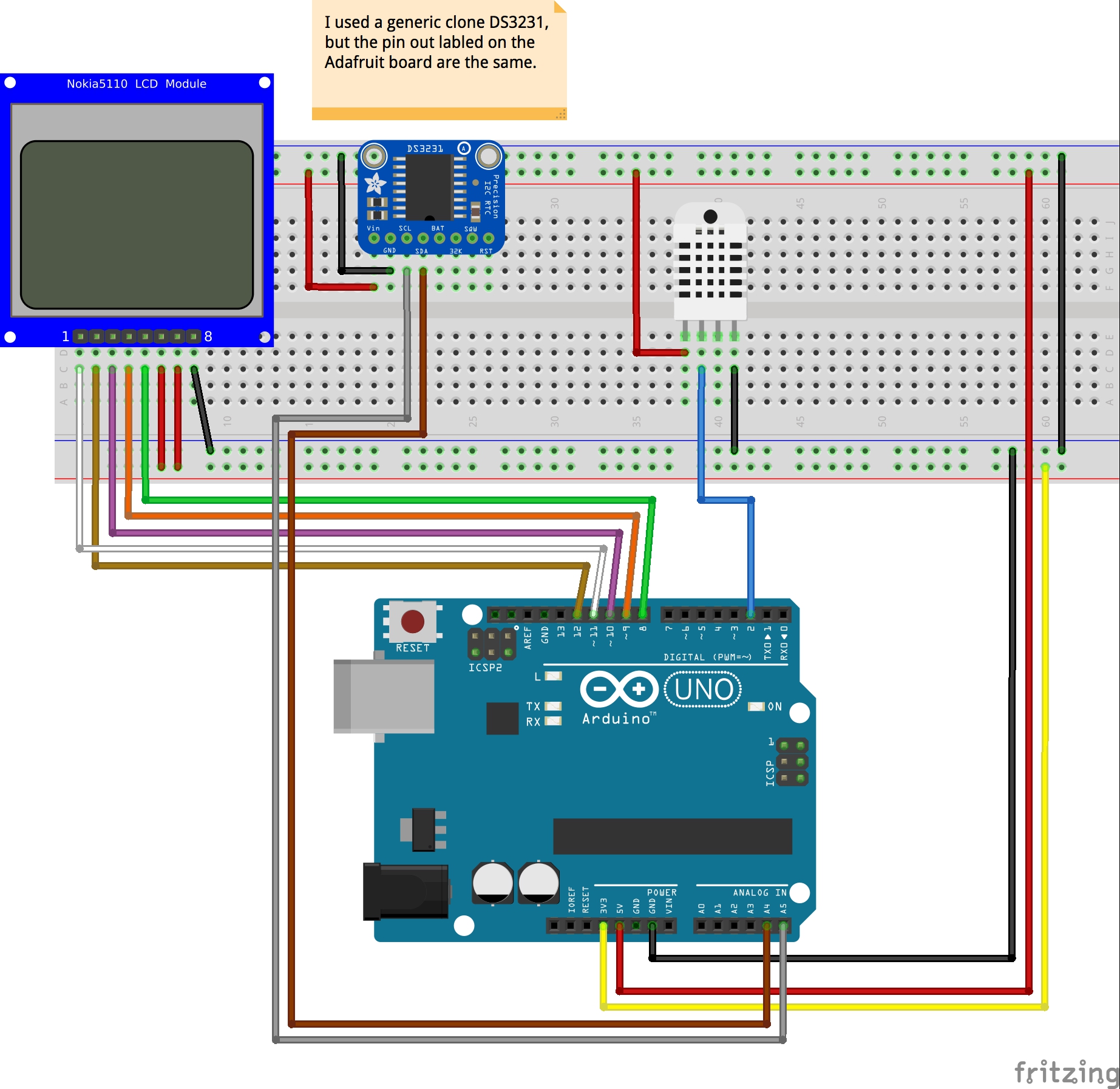
I started wiring with the LCD 5110. It has 8 pins. The chart above show which pin of the LCD needs to connect to the Arduino. Also the screen runs off of 3.3v, make sure you don't connect it to the 5v line. While the screen is small, about 1.5", it is 84x48 pixels which can be used for text, graphics, and bitmaps.
For the LCD 5110 I used the LCD5110_Basic and LCD5110_Graph libraries. You can find them at http://www.rinkydinkelectronics.com/library.php?id=44
Here is how I have it wired up.
- RST -> Arduino PIN 12
- CE -> Arduino PIN 11
- DC -> Arduino PIN 10
- DIN -> Arduino PIN 9
- CLK -> Arduino PIN 8
- VCC & BL -> 3V3
- Gnd -> Ground
The DHT22 is a cheap, good, general purpose sensor for temperature and humidity. The DHT22 is pretty straight forward to install. The ground pin goes to ground, the power pin goes to 5v, and start with a 10k resistor between Vcc and the data pin. I had to remove the resistor before I began to see data come through. The DHT has 4 pins, but only 3 are used, they are charted here, pins going from left to right
- Vcc (3.3 -5v)
- Data
- Not Connected
- Ground
Pin 1 is connected to power, 5v. Pin 2 is our data pin, I connected it to Pin2 of my Arduino. Pin 3 is not used and Pin 4 is connected to ground. Here is a link to the library I used https://github.com/adafruit/RTClib
DS3231 Real-Time ClockWhile the DS3231 is wired up and the Arduino can see the device, but I am having problems getting any of my boards or various libraries to work with it so far. I have 2 additional ones on order which should be here in the next week or two I will update the project when they arrive. And while I am thinking of it, this sketch comes in handy when trying to troubleshoot some sensor issues. Here is a link to it. http://playground.arduino.cc/Main/I2cScanner
The pinouts for the DS3213 are as follows:
- 32k
- SQW
- SCL
- SDA
- Vcc
- Ground
Pin 6 is connected to ground, Pin 5 to 5v, Pin 4 to A4, Pin 3 to A5. (pins A4 & A5 are the analog pins on the Arduino).
So far I have a working temperature sensor reporting temperature and humidity. The display is simple to this point, it just displays the temperature, delay, clear screen, and then print the humidity and all over again.
Work needs done on the formatting for the data on the screen. While the screen looks small, there is quite a bit of real-estate to work with. I found a great library and documentation at http://www.rinkydinkelectronics.com/library.php for the LCD5110. It is some of the best documentation I have run across to learn how to work with various libraries and functions (remember I am new to this).
With everything wired up, I started with a sketch from the wild (I would provide credit, but the code wasn't commented and I have been to sooooo many sites.) The sketch is reading the temperature and humidity from the DHT22 and displaying it on the LCD 5110.
During a project I can get side-tracked by "add-ons" if you will. Since I am planning to keep this as the indoor/test unit, I figured it should look nice and at the same time give me a chance to clean up the rats nest of wires I have assembled. And time to take an extra picture or two and make sure my notes are updated.
I always have some wood laying around our house. I rummaged for the perfect piece. Using a 7/32" drill bit, I drilled holes aligned with the Arduino holes. I took the nuts from the M3 - 12mm screws and super glued them in the holes. With 1/4" nylon spacers I mounted the Uno to the board. Next up the breadboard, but that was the easy part.
Next, onto the layout. I figured now was a good time to look at the placement for the various parts. Only 2 now but with 2 more on the way (BMP280 and ESP2866).
The layout looks like it should provide room for the BMP and ESP. If not, time to take it apart again and start again. Lastly I needed to do something with the wiring. I am not normally too anal-retentive about how it looks, but the more I work in this hobby/field the more I like to keep things neat. Not only does it make it nicer to look at, but when troubleshooting or adding new parts it really helps.
All is wired back up again and working. Now it is time to work on the code while I wait for the other parts. The code is not complete from my standpoint, I want to work on how the information is displayed on screen and how changes are updated. I am trying to decided and figure out how to display a historical graph at the bottom of the screen. I will post my code and any updates will appear on my github site.
When more parts arrive, I will continue on with the project. Until then I hope you enjoyed seeing what I am putting together. Some of the items I have on my agenda are to:
Phase Scope Creep - what's to come. . .
- Order Nano to reduce size for outdoor case
- Researching the use of a NodeMCU for the outside controller
- WeMos D1 mini pro
- Barometric pressure sensor
- Research weather math
- Wunderground account and share data
- Solar panel(s) and rechargeable battery for outdoor unit


Comments