

Hardware components | ||||||
| × | 1 | ||||
| × | 2 | ||||
 |
| × | 1 | |||
 |
| × | 1 | |||
 |
| × | 1 | |||
Software apps and online services | ||||||
 |
| |||||
For this project I pulled out my Adafruit Metro Mini 328. I am a sucker for a dev board of almost any flavor. In fact, I also have an ItsyBitsyM4 Express that I am going to port over the Arduino-based clock over to CircuitPython.
The MM2xOLED_RTClock
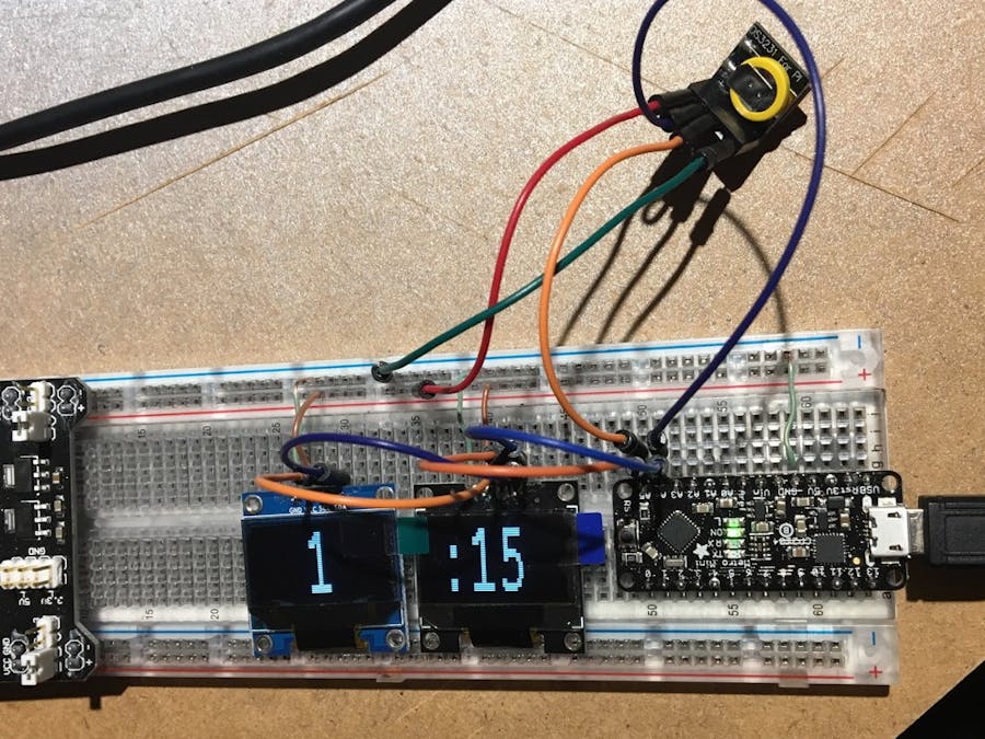
I was in need of a simple clock for a room that has none. I started to rummage through my bins and drawers and came up with a few items. In one drawer I found two SSD1306 128x64 OLEDs. One display hours on and minutes on the other. And since they are both I2C it should be easy peasy to make they both work together. A third would be nice for seconds and am/pm indicator. That is version 1.5 of this project.
BOM
- 1 x Metro Mini 328 or an Arduino-compatible board
- 2 x SSD1306 OLED 128x64 screens
- 1 x DS3231 real-time clock
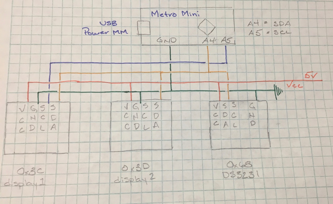
Wiring
display1, display2, RTC SCL --> MM pin 5
display1, display2, RTC SDA --> MM pin 4
The MM is powered via USB.
Both displays and the RTC is power via a 5v breadboard power supply.
There is a common ground run between the breadboard ground rail and the MM Ground pin.
StoryFor this project I pulled out my Adafruit Metro Mini 328. I am a sucker for a dev board of almost any flavor. In fact, I also have a Express M4 that I am going to port over the Arduino-based clock over to CircuitPython.
I was in need of a simple clock for a room that has none. I started to rummage through my bins and drawers and came up with a few items. In one drawer I found two SSD1306 128x64 OLEDs. One display hours on and minutes on the other. And since they are both I2C it should be easy peasy to make they both work together. A third would be nice for seconds and am/pm indicator. That is version 1.5 of this project.
When I started to connect everything up, I soon realized (doh! moment) they are both the same address. Ok, this should be easy enough, pull off and / or add a resistor if my memory serves me right. And it did. They are little, itty-bitty, resistors; put on with lead free solder. I have noticed that with the lead free I have to crank up the heat to work with it at all. The blue one I could find information on, so changed the address on it. With a little work I was able to get the 0x78 resistor free and a solder bridge 0x7A to change the address. They are found in the upper left-hand corner on the back of the screen. Now with two separate addresses it is quite easy to control the displays. Now the blue one is 0x3D and the black 0x3C, the stock address.
The second screen I have I can’t find a data sheet for. There are no part numbers on it and I don't remember where I picked it up from. I am assuming that R3 or R4 are used to change the address, but I was not able to confirm it. I did try and quick solder bridge, but then it didn’t work at all. I pulled the bridge and it worked again. That one stayed with the stock i2c address.
I went digging into setting up the DS3231 real-time clock. It gave me some fits trying to set the time, but it got there. I was curious to see that when I was coding that I didn't have to setup the address for the RTC, yet is was always there and working. I roamed through the RTClib.h file and saw that, yup, the address is preset in the library. It seems that all DS3231s must use the same address. Fine by me and good to know.
I would like to add a third screen as to display the seconds, date, or other information. In order to use more that 2 a new library is in order, MultiOLED along with another library will allow multiple displays across multiple GPIO pins using a single I2C clock. It is really quite ingenious. A third screen was just order and when it comes in it will be added to the clock!
Here is the "It works on my setup" code, so your milage may vary. You can find it over in my GitHub repo MMOLED_Clock.


Comments