


OK, here's the dealio, m'peeps.
THIS DOESN'T WORK (yet), but am committing to getting this done at some point. I'm close enough though that if you want to get to where I'm at 80%-90% done and want to do some good old fashioned PIC assembly, you can crank out a handy little chip that will glue a BBBW or an R-PI to 8 servos or ESC (electronic speed controls).
Check out the firmware source code...it will compile and with some tweaking, will drive 8 servos and even 5 LED/TTL signals.
The diagnostic program for it also works. If you have a language that can pump out 2 bytes over RS-232, you can use this chip. It is proprietary, but still I want you to have the source code because we are all brothers here. Here is the installer ( VB.NET ) for it:
note: had to remove the link until I get it checked out. Will post as soon as I get it squared away.
Its just the stock installer so should come off perfectly on uninstall.
How it works
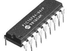
To use the chip, buy a stock PIC16F88 (only about $2-$3) from Mouser or somewhere. Get a 20-cent 20 Mhz crystal for it too, and you are locked cocked and ready to rock (no other external discretes necessary for core operation).
Compile the source code to a HEX file and get a K150 or a PICKit3 and program the PIC chip with it. (How you compile...no scratch that...ASSEMBLE is the correct term here, is you go to microchip.com and download MPLABX (it comes stock with just the Assembler btw). It's FREE, dump the source code into a "stand-alone" project and assemble to hex file. It'll be in dist...sumthin...sumthin BUT IT WILL HAVE the name S3.hex.
Firmware Architecture
How it works internally is with a serial communications "front-end" (hardware UART RX only) that just sets 13 internal registers that hold on to the current values of each of the hardware channels out. The "back-end" services the chip (as servos require constant supervision) just reading off of these set registers translating them to the PWM and TTL levels to drive the servo signal lines and the LED's...via "instruction counting" and a main loop that synthesizes multitasking through careful timing.
Use
I would develop a quick and dirty board for it to that breaks out the PWM lines to 3-pin 0.1" headers (run the 0 and +5VDC along rails so each output is servo-ready) as well as putting the current limiting resistors/LED's on the remaining lines (1K resistors typical). Then use that voltage-divider-type network that everyone knows is how you get your PC (via RS-232) to talk to a PIC (receive only supported in the S3, which is OK because you aren't going to drop any bytes going that short a run, and chances are any bad codes will be over written in the next new milliseconds anyway).
Theory of Operation
Hobby servos and ESC's take as their control signal a specific kind of PWM that is kind a "chirp" between 1 ms and 2 ms (aka 1000 us to 2000 us) long with the proviso that the next chirp arrives in about another 40 to 100 ms (that's milliseconds, or 1000's of a second). so max deflection zero is 1000 us and max deflection maximum is 2000 us with neutral holding at 1500 us.
The S3 takes a 1-byte value so you have a resolution of 255 positions you can move the servo to (or throttle the ESC). The protocol is easy to understand to talk to the 3D you send a 1-byte address (0x01 for servo PWM channel 1, 0x02 for channel 2, etc. etc.) and then a byte for the value you want to set that internal register to. The chip handles the housekeeping to supply the servo the signal it needs continuously.

Comments