The Little Red Box (LRB) contains a Photon from particle.io with attached soil moisture, soil temperature and a UV/IR/Visible light sensor. It uploads data to data.sparkfun.com and dweet.io for storage. The Phant server at sparkfun allows viewing of tabular time stamped data and supports data downloads in a variety of formats to include csv files that can easily be imported into Excel. Freeboard.io can be used to pull data from dweet.io and allows the creation of a variety of custom graphic displays. Students and teachers can deploy the LRB in the school garden or other locations around campus in order to collect data and perform experiments. The generated time-series data can be view from a computer in the classroom or from home. Students and teachers also have the ability to customize their own dashboards at Freeboard.io using the LRB data stream. You can visit smartgarden.io to learn more about applications and related curriculum.
Building the LRB.
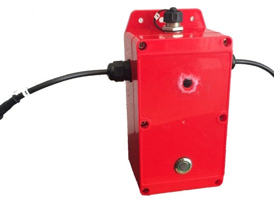
Three holes need to be drilled in the base sides of the red box. Two of the holes are for the cable glands and one is for the waterproof mini-usb connector. Two holes need to be drilled in the top of the red box to accommodate the on/off green LED button and the fused silica glass window. Fused silica glass is used because it passes UV unlike regular glass. Since the fused silica glass has a diameter of 1/2 inch I used a 3/8 inch hole. Mount the glands and the usb connector on the base of the box. Mount the button on the lid.
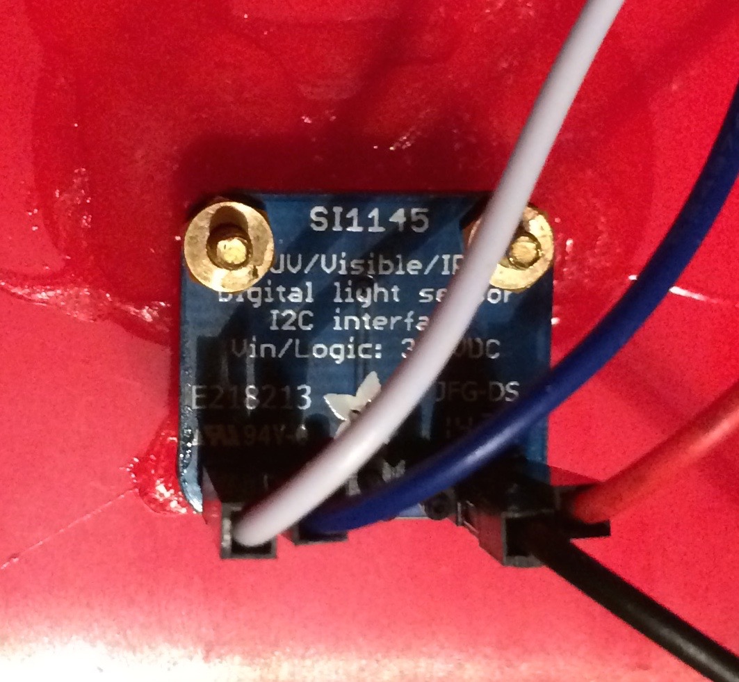
A mounting for the SI1145 breakout board is needed. I used two #2-56X.5 inch brass screws that just fit through the mounting holes on the breakout board. Using four brass nuts and the screws you can mount them on the breakout board with the screw heads extending well above the sensor board on the side with the sensor. I used a third screw and two nuts to balance the sensor in the next step. Using a fast drying two part epoxy you can then mount the two screw heads to the red box lid taking care to center the sensor chip in the fused silica glass window. The sensor is located in the center of the breakout board. Use some sand paper to rough up the plastic where you will apply the epoxy. Note that it might take two applications of epoxy to create a solid mount for the breakout board. After the epoxy has cured you can remove the temporary balancing screw and adjust the brass nuts to bring the sensor chip as close as possible to the fused silica glass window. Make sure that the upper nuts are tight so the board does not move.
SI1145 breakout board mounted to the inside of the box lid.
I used clear silicone caulk to mount the fused silica glass centered on the hole on the exterior of the lid. I first added a small amount of silicone caulk around the hole and then carefully placed the silica glass window on top and applied gentle pressure. After allowing the caulk to dry I added additional caulk around the perimeter of the silica glass to insure a firm seal.
Fused silica glass mounted on the top of the red box lid with silicone caulk.
Next you can mount the lithium ion polymer battery inside the lower box. I used two 1/4" cable clamps, two #4-40x3/8" screws and 2 washers to fix the cable clamps to the read of the lower box (opposite end from the USB connector). Cable ties can be looped through the cable clamps and around the battery to secure it firmly in place.
Battery firmly secured to the lower red box.
You can now feed both cables from a pair of the waterproof 4-pin connector cables through the glands mounted on the lower red box. You will probably want to expose another inch of the 4 conductor wire as several of these will need to be soldered.
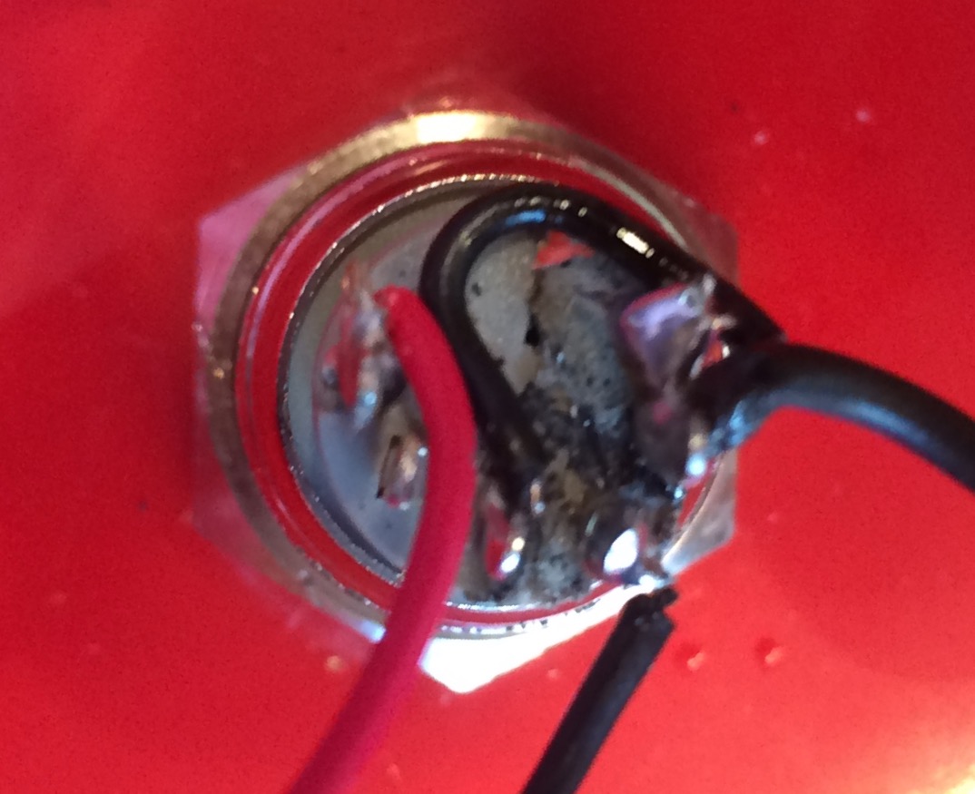
The cable connected to the JST connector from the battery needs to be cut mid-way between the battery and the connector. All of the red positive power lines from all three sensors should be soldered together along with a positive red wire that should be soldered to the positive terminal of the green push button on/off switch mounted on the box lid. Be sure to protect the collection of soldered wires with shrink tubing. Note that you can use a red female jumper cable with the male end removed (soldered to battery positive) to connect to the SI1145 VIN pin on the breakout board.
The negative wire from the battery is routed to the common terminal of the push button switch. The normally open terminal of the push button switch is connected to the LED negative terminal on the green push button switch. This same normally open terminal also should be connected to the negative side of the (black wire) coming from the JST connector. You will need to supply this black wire and insulate your solder connections with shrink tubing.
A blue and a white male/female long jumper cable can be used to connect the SI1145 to the SDA and SLC connections on the Photon battery shield.
Connections for the temperature probe include power (red wire) and ground (black wire) and the signal line (usually a white or yellow wire). Note that the signal line is connected to input D4 on the Photon. Note also that the signal/data line requires a pull up resistor to VIN. Normally this resistor should be 4.7 k Ohms but I found that a 3.3k Ohms resistor produced more reliable results. This might be due to the length of the cable between the Photon and the temperature probe as well as the fact that the LRB is powered by a 3.7v battery instead of a 5V source. In this case I attached the 3.3k Ohms resistor directly to a male jumper that was soldered to the signal/data line with the other end of the resistor soldered to the common VIN red power connection.
For the moisture probe I used the SparkFun moisture sensor, a six inch piece of 3/4 inch PVC nipple (threaded on both ends) and two 3/4 inch PVC caps (the PVC parts can be purchased at a hardware store). In one cap I mounted a cable gland by drilling an appropriate size hole to insert the cable gland. In the other cap I used a Dremel drill and a small bit to route out a rectangular hole in the cap through which I was able to push through the soil sensor. I then used epoxy to fix the soil moisture sensor in place. I also had to extend the wires that come with the sensor so they were long enough to mate with the waterproof 4-pin cable/connector that was fitted through the cable gland at the other end of the PVC nipple.
You will need to add a three or four conductor cable with attached waterproof 4-pin connector cables at each end which is then connected to the LRB and the moisture probe. Note that the red positive power wire of the soil moisture sensor is connected to D5 on the Photon battery shield. This allows power to be applied only when a sensor reading is taken and preserves the life of the soil moisture sensor. The data line from the soil moisture sensor is connected to Analog AO and the moisture sensor black ground wire is connected to system ground.
For the temperature probe you can connect (solder and use shrink tubing) a waterproof 4-pin connector cable to the end of the waterproof soil temperature sensor. The soil temperature sensor comes with sufficient cable so you should not need to add additional cable. The data signal line is connected to D4 on the Photon battery shield and the red power line is connected to VIN while the black ground line is connected to system ground.
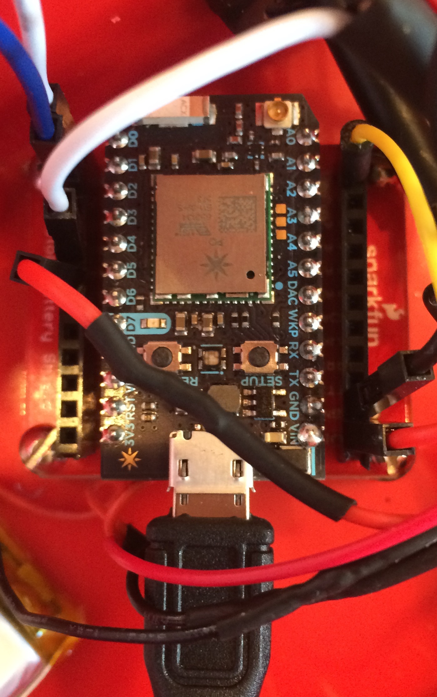
You can now mount the battery shield by using the #4-40 3/8 inch screws and the #4-40 nylon standoffs on three of the battery shield mounting holes. Use one of the #4-40 3/8 inch screws in the fourth hole to attache the battery shield to the base of the LRB about in the middle of the box.
Insert all of the jumper cables from the sensor in their appropriate location on the the Photon battery shield Connect the micro USB end of the the micro/mini USB cable into the micro USB connector on the Photon and connect the other end to the mini USB connector on the inside of the LRB. You are now ready to run the I2C Address Scanner in order to obtain the hardware address of the temperature probe. This address will be used in the main LRB sketch. You should be able to connect a min USB connector to the LRB and the other end to your computer in order to monitor serial communications with the Photon. The USB connector is also used to power the LRB and to recharge the battery. You can use a standard USB charger for this purpose. In my case I used a spare iPhone or iPad charger but any standard USB charger will work for this purpose. Note that while charging you will need to turn the LRB pushbutton to the on position in order for the battery to charge.
Below you can see a picture of the LRB deployed in a school garden. You can see examples of the LRB in use as well as some curriculum and web links at smartgarden.io.


_3u05Tpwasz.png?auto=compress%2Cformat&w=40&h=40&fit=fillmax&bg=fff&dpr=2)
Comments