

Hardware components | ||||||
| × | 1 | ||||
 |
| × | 2 | |||
 |
| × | 2 | |||
 |
| × | 5 | |||
Software apps and online services | ||||||
 |
| |||||
It would be nice to communicate with an Arduino thru RESTFUL interface and I found this aREST framework. As described on its website (arest.io), the aREST framework is a complete solution to build powerful RESTful applications based on the Arduino & the Raspberry Pi platforms. It can handle all kind of communications via Serial, WiFi, Ethernet, and much more.
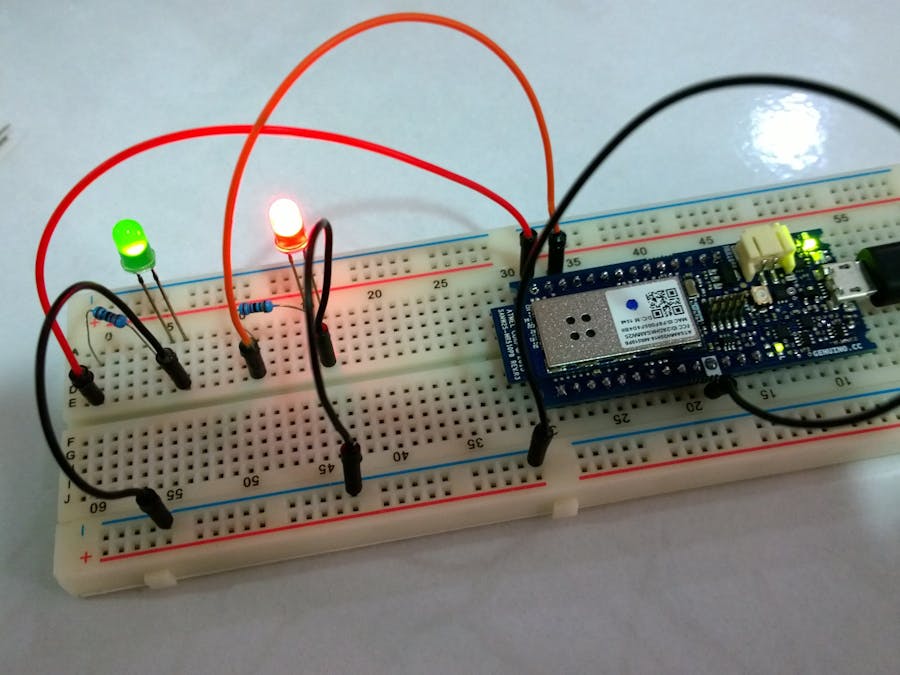
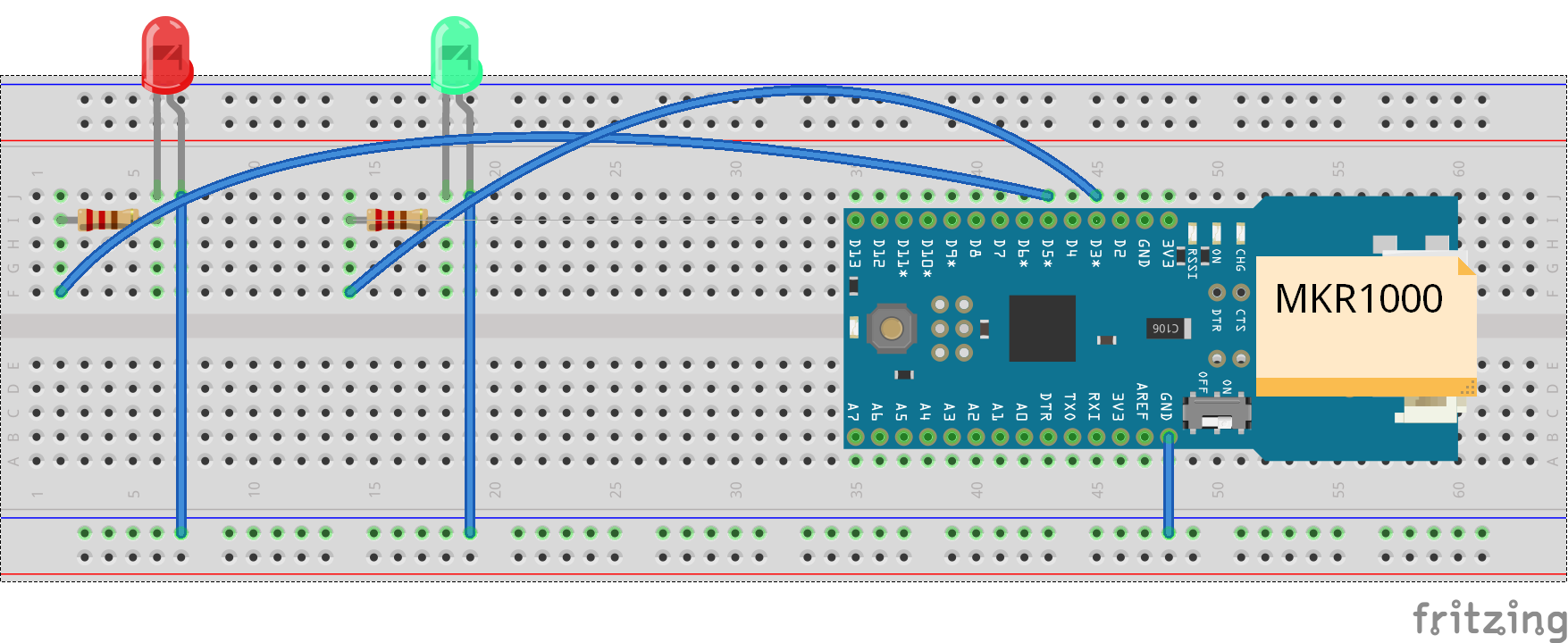
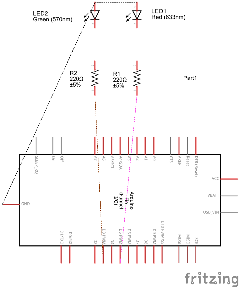
In this project, I will show how to setup MKR1000 with 2 LEDs and you can control the LEDs via REST API.
Steps to setup the dev environment1. Setup the MKR100 using this Getting Started guide.
2. Install Wifi101 library using Sketch > Include Library > Manage Libraries ... menu. (Note: I am using Wifi101 version 0.9.0)
3. Install aREST library. (Note: I am using aREST version 2.1.1)
4 Make the following changes to aREST.h:
- Change
WiFi_htoWIFI_H - Change the following
void addToBuffer(float toAdd) {
  char number[10];
  dtostrf(toAdd, 5, 2, number);
  addToBuffer(number);
}
to
void addToBuffer(float toAdd) {
  char number[10];
  sprintf(number, "%5.2f", toAdd);
  addToBuffer(number);
}
5. Copy the sketch from the code section below.
6. Setup the board and LEDs.
7. Compile and upload the sketch.
About the sketchCreating a WiFiServer instance listening to port 80:
WiFiServer restServer(80);
Setting the device ID and name:
// Give name and ID to device
rest.set_id("008");
rest.set_name("mighty_cat");
The loop() is simple, just listening to port 80 and handling incoming connection:
void loop() {
  // Handle REST calls
  WiFiClient client = restServer.available();
  rest.handle(client);
}
Exposing the custom function ledControl(String) within setup():
// Function to be exposed
rest.function("led",ledControl);
This is the ledControl(String) function:
// Custom function accessible by the API
int ledControl(String command) {
  Serial.println(command);
  // Get state from command
  int state = command.toInt();
  digitalWrite(5,state);
  return 1;
}
Finally the printWifiStatus() function:
void printWifiStatus() {
  // print the SSID of the network you're attached to:
  Serial.print("SSID: ");
  Serial.println(WiFi.SSID());
  // print your WiFi shield's IP address:
  IPAddress ip = WiFi.localIP();
  Serial.print("IP Address: ");
  Serial.println(ip);
  IPAddress subnet = WiFi.subnetMask();
  Serial.print("Netmask: ");
  Serial.println(subnet);
  IPAddress gateway = WiFi.gatewayIP();
  Serial.print("Gateway: ");
  Serial.println(gateway);
  // print the received signal strength:
  long rssi = WiFi.RSSI();
  Serial.print("signal strength (RSSI):");
  Serial.print(rssi);
  Serial.println(" dBm");
}
Open the Serial Monitor using Tools > Serial Monitor menu and note down the IP address shown.
Display the device ID and name:
To turn on pin 5, type the following to the web browser:
http://<ip-address>/digital/5/1
To turn off, type
http://<ip-address>/digital/5/0
To turn on using exposed function, type
http://<ip-address>/led?params=1
To Find out More About aREST
Refer to the aREST Arduino library page on GitHub


Comments