

Hardware components | ||||||
 |
| × | 1 | |||
 |
| × | 1 | |||
 |
| × | 1 | |||
Software apps and online services | ||||||
| ||||||
 |
| |||||
This tutorial aims to present a low-cost alternative for developing Internet of Things application (Internet of Things - IoT), integrated with Microsoft Azure using Mobile Services. The ESP8266 is a module that integrates a small microcontroller with a 802-11 transmitter WIFI a / b / c / n, and the datasheet is here. Following this tutorial we will use the ESP8266-esp1 which consists of a simple and inexpensive module, costing about $ 3 to $ 4 if purchased directly from China. The great advantage of this module is the ability to program it by installing a call NodeMCU firmware and program it using Lua to operate as an internet of things device.
What is necessary:
- ESP8266-ESP1
- Raspberry Pi B+
- Temperature / humidity sensor DHT11
The Raspberry Pi will be used as interface for programming ESP8266, since their gates are sensitive to 3.3v not supporting greater stresses that for this reason that most Arduinos can not be integrated directly with the ESP8266. To integrate with the Arduino platform is necessary to seek special versions that support serial signs on the pins TX / RX to 3.3v.
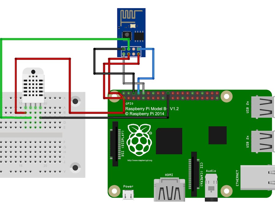
The first thing we need to understand is the pinout of ESP8266-ESP01. As I said before it needs to be fed with 3.3v on the door VDC and enable port that is responsible for enabling the operation of the transmitter. The TX and RX ports are connected in inverted form with the ports TX and RX Raspberry Pi and finally just connect the GND port on one of the GND pins of the Raspberry Pi. Note that in this model you will still have two GPIO ports to use in your application.
As described this is the basic electrical setup for direct connection to the Raspberry Pi to see if it's all right, connect the Raspberry Pi to a monitor, keyboard and power supply and then in the console Raspbian enter the bold command:
pi@raspberrypi ~ $ ls /dev/tty*
Then observe the result displayed on the console if the port / dev / ttyAMA0 was created, it indicates that the connection was successful.
The next step is to make a connection through a serial terminal client like picocom, you must first perform the installation through the bold command:
pi@raspberrypi ~ $ sudo apt-get install picocom
To trust the connection type the following command in bold:
pi@raspberrypi ~ $ sudo picocom /dev/ttyAMA0 --omap crcrlf --b 115200 --p n --d 8
After the connection is made type: at <ENTER>
If everything is correct, the module will return OK indicating that this working. If you want to use the integration of ESP through serial AT commands, https://github.com/esp8266/at-command-set this github has a list of basic commands that can be used.
Firmware Upgrade NodeMCU
For the upgrade must first install a tool called: esptool which is nothing more than a Python program that makes updating the firmware ESP8266 based on a binary file. Before you download the esptool need to install the serial library python through the bold command:
pi@raspberrypi ~ $ sudo apt-get install python-serial
To download the ESP8266 just type in Rasbian terminal this command:
pi@raspberrypi ~ $ wget https://github.com/themadinventor/esptool/archive/master.zip
And to unpack:
pi@raspberrypi ~/Desktop $ unzip master.zip
The esptool-master folder is created using the command to access: cd esptool-master
The next step is to download the image of the updated NodeMCU, which can be found on github (https://github.com/nodemcu/nodemcu-firmware/releases)
In this example I'm using the nodemcu_float_0.9.6-dev_20150704.bin image that should be saved within the esptool-master folder.
Pay Attention:
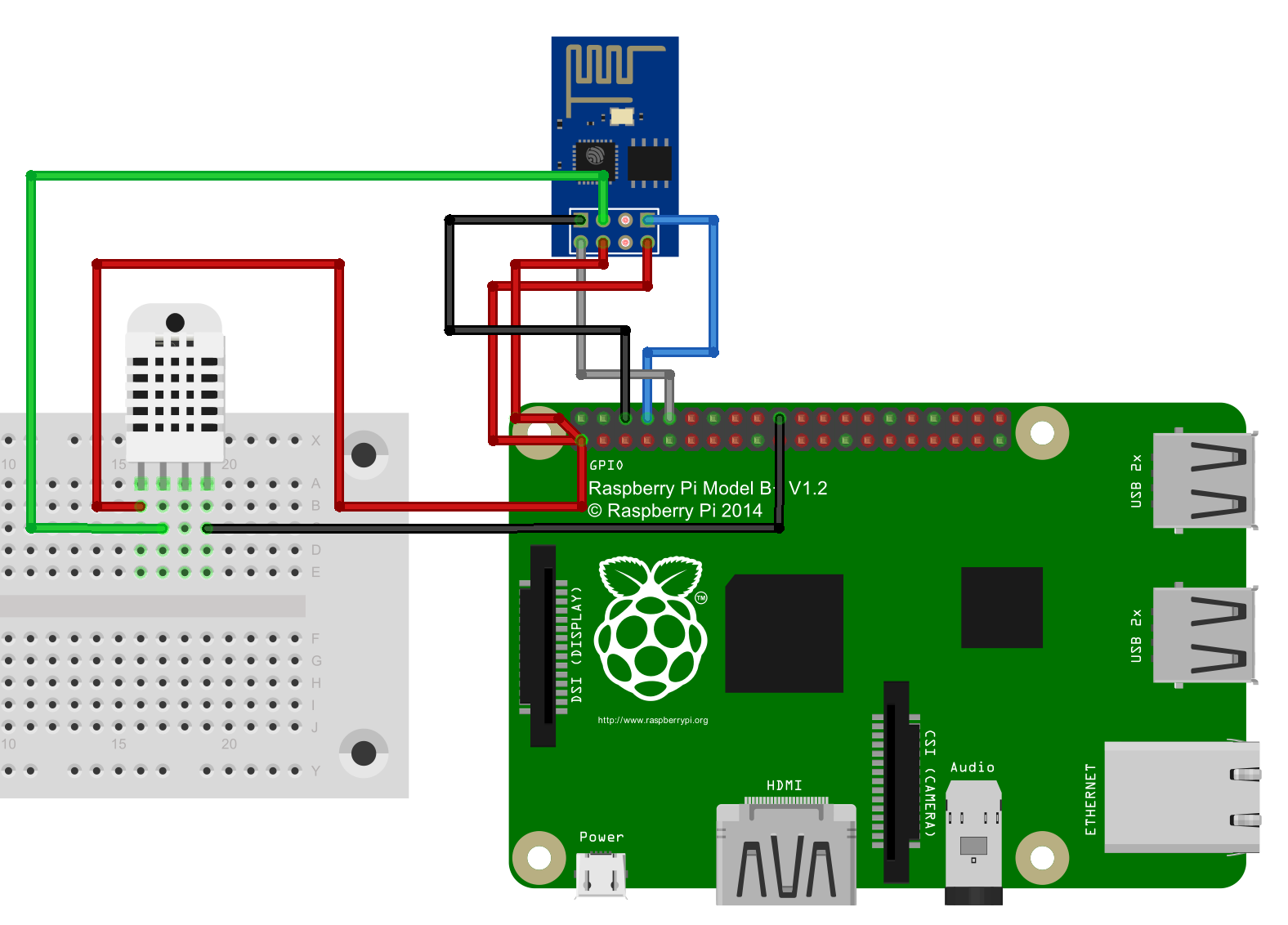
Before performing the upgrade FIRMWARE you must place the ESP8266 recording module for this you must modify the wiring diagram connection with the Raspberry Pi as the following picture, connecting the GPIO0 in a GND port.
Now simply run the raspbian terminal the following command in bold to update the firmware:
pi@raspberrypi ~/esptool-master $ sudo python esptool.py --port /dev/ttyAMA0 write_flash 0x00000 nodemcu_float_dev_json_20150317.bin
If it has successfully passed, the result will be identical to the console above. The next step is to disconnect the cable VCC pin module and also disconnect the cable that connects the GPIO0 to GND, then reconnect the VCC cable to the module.
Programming NodeMCU
We can now start programming the ESP8266 módudo, but you do need to download the ESPlorer http://esp8266.ru/esplorer/ which is an application written in Java to program more simply the NodeMCU. Now in the graphical Rasbian interface, open a terminal window, access the directory where you unzipped the file and type:
java -jar ESPlorer.jar
To verify that the connection to the ESP8266 can be made, click the right button of OPEN interface and then click the button "Info Chip", the console display information communication is correct.
Circuit for the sensor is described in the following image, despite the white color, the sensor on the breadboard is the DHT11 where the pin is (VCC-Sign-ND-GND) for this reason that the VCC is connected to 3.3v, Raspberry GND and the signal Pi and the GPIO port 2.
Source code to read the sensor and send the moisture data to the server is available in: About https://github.com/waltercoan/br.univille.esp8266.azure source we have two programs in LUA language, which init.lua is responsible for making the connection to a WIFI access point and then this program runs dht11.lua that is effectively responsible for reading the sensor values, and perform a HTTP call to the Azure server. Important to note that this code is a code of adjustment provided by the site: http://www.labviewarduino.in/2015/05/export-temperature-data-to-thinkspeak.html
init.lua
In this first code you must modify the third line to include the name of the access and password authentication.
print("Setting up WIFI...")
wifi.setmode(wifi.STATION)
wifi.sta.config("WIFI_NETWORK_NAME","PASSWORD")
wifi.sta.connect()
tmr.alarm(1, 1000, 1, function()
  if wifi.sta.getip()== nil then
    print("IP unavaiable, Waiting...")
  else
    tmr.stop(1)
    print("Config done, IP is "..wifi.sta.getip())
    dofile("dht11.lua")
  end
end)
dht11.lua
In this program is all the logic for reading the temperature sensor / humidity and sending through HTTP request to the Microsoft Azure. The http request is the only part that needs to be customized, you need to modify the table name in the example is humidity, the authentication key that will be provided by Azure and the application host in azure. Another possible improvement is in addition to sending the humidity is also sending the temperature calculated by the sensor. Documentation according to the site: https://msdn.microsoft.com/en-us/library/azure/jj677200.aspx details how to build HTTP Rest of the Mobile Services API call that was used in this code.
function sendData()
  getTemp()
  conn=net.createConnection(net.TCP, 0)
  conn:on("receive", function(conn, payload) print(payload) end)
  conn:connect(80,'191.236.80.12')
  conn:send("POST /tables/humidity " .. "HTTP/1.1\r\n")
  conn:send("Accept: application/json\r\n")
  conn:send("X-ZUMO-APPLICATION: AZUREKEY \r\n")
  conn:send("Host: plantuniville.azure-mobile.net\r\n")
  conn:send("Content-Length: 18\r\n")
  conn:send("\r\n")
  conn:send("{ \"value\":\"" .. Humidity.."."..HumidityDec.."\" }")
  conn:on("sent",function(conn)
    print("Closing connection")
    conn:close()
  end)
  conn:on("disconnection", function(conn)
    print("Got disconnection...")
  end)
end
tmr.alarm(2, 60000, 1, function() sendData() end )
Mobile Services Windows Azure
The next step is to create a mobile services on the Microsoft Azure to receive sensor data. After logging into Microsoft Azure Mobile Services and click on the NEW button.
On the next screen enter the name of the mobile service service that should be the same as reported in the request http host. Select the Create a free database and the region where the bank will be installed. In the second stage of this screen set the database password and confirm the creation of the service.
The next step after creating the service and create a table in the database that will store the data for this within the mobile service created, click data and create a new table as the following image. On the screen to create the new table enter the name that should be the same as the http request. The permissions choose anyone with the application key.
Now to complete need to retrieve the key that permission to access the REST API that mobile service has just been created. To do this click on your mobile service created and the main screen click on the Manage Keys button. The value that is displayed in the Application key field that must be placed in dht11.lua source code as the previous step.
Deploy the code to ESP8266
The deployment process of the two programs (init.lua and dht11.lua) is greatly simplified because the use of ESPlorer. Repeat the previous step to run the ESPlorer, and set the connect button to connect to the module. Then simply click the open icon, select the file dht11.lua (which should already be within the raspberry pi SD), and then activate the Save button to ESP. You will see that in the log window next to line by line of the program will be sent to the module.
The last step is to load the init.lua file, which consists of repeating the previous steps for this file. Upon completion of the upload you will observe that the program will run automatically.
While the ESP8266 module is operating check the database table of their mobile service to verify that data is being recorded. Now you can continue this example building a web interface to publish the data using the same Rest API.
If you would like to continue studying IOT applications suggest watching the following courses in Microsoft Virtual Academy:
Internet of things dal tuo sensore a microsoft azure
A internet das coisas - Fundamentos de IoT


Comments