


Introduction
Lattice recently introduced the MachXO4 FPGA.This is a flash-based small field programmable gate array (FPGA) and supports from 1K to 10K of Logic (LUT’s) in small devices.
The MachXO family has been a round for a very, very long time, and is probably one of the most used FPGA’s ever in the industry. The XO4 is very similar to its predecessor XO2 and XO3, however it comes with an very interesting advantage: It’s supported in Lattice last generation toolchain : Radiant.
Risc-V
This tutorial shows the steps in the Radiant Tools chain to create a softcore Risc-V controller on an FPGA. Soft-cores are used a lot in programmable logic to do the low-speed control and house-keeping, and create a more flexible platform inside the chip.You more or less can create your own core and peripherals, which makes it fun to use.This tutorial does not go deeper into the FPGA architecture or Risc-V, but you can find more interesting links in this section - more info
Hardware
This Tutorial is using the MachXO4 evaluation board : LFMXO4-110-EVN
This eval-boardhas the 10K logic FPGA, and supports multiple IO expansion ports like Raspi, Arduino, Versa, Aardvark. It supports also the ASC-10 Power monitoring chip, switches, buttons, Leds and a 7seg display.Interfacing is via USB : the FTDI chip on the board creates 2 interfaces: one to the JTAG programming interface, and one to the I2C bus interface.We use the programming interface in this tutorial.
Remark: This Tutorial you can run on any Lattice Eval board with FPGA supported in Radiant, at the end its a matter of adapting the pin-constaint file.
Tutorial Steps for creating your soft-core
We follow the following steps:
- 1. Install the free software.
- 2. Create the softcore system, based on a existing template
- 3. Create the Risc-V software / firmware
- 4. Create the complete system on chip by mapping and routing it on the silicon
- 5. Program the FPGA on the Demo board and see the result
See this appendix section A to install the toolchain and the dependencies
Follow the Radiant training video to get yourselves familiar with the screens and setup Do the same for the Propel training to understand the basics of PropelSee appendix section B
Step 2 : Build the Softcore SystemBefore opening Propel Builder, create a workspace directory where your design will be locatedMine is <C:..>/my_workspace/.From here we create a Hardware design section and a Software design section.Now open Propel builder and select “file -> new soc design”, this window pops up :
Create the project name and be sure its in your workspace directory. We keep it in Verilog language.
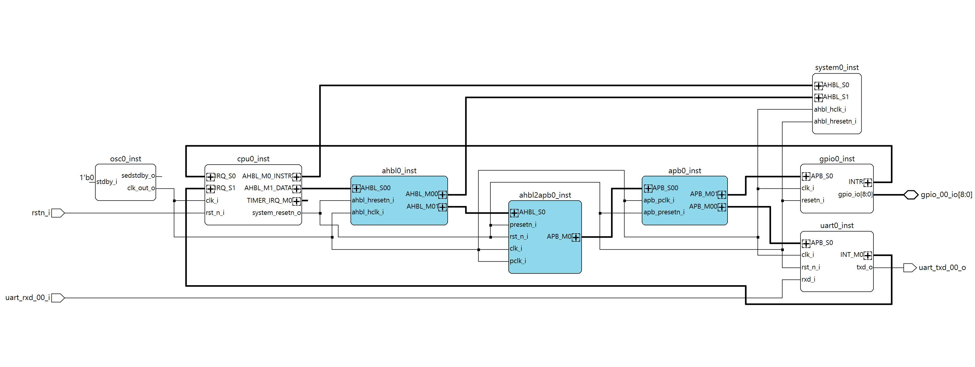
Next : Select the template: Scalable Risc-V SoC project, Next : Select the general state machine -SM- core versionNext : Select device, in this case LFMXO4-110HC in 484 packageNext: Select peripherals, first ‘confirm’, then keep the1 UART and the 1 GPIO Next: You get an overview of the bus structure, incl the memory mapped addressesNext: You see the project information and locationFinish : Propel Builder is creating the project for you, and show this schematic view:
The blocks explain them selves, every block is an IP code instantiation, you can view them deeper in the Design View section.You can double click on the blocks and adapt the IP-block settings and generate a modified block if you like (like adapting Osc-frequency, or add IRQ’s to the CPU or expand the number of IO’s I the GPIO peripheral etc.)IF you adapt the Osc-speed, don’ t forget to re-generate the Uart block to get your baud-rate correct!)You can also modify the design by adding IP or snippets – see IP Catalog section.There is even a IP Packager tool, where you can generate compatible IP-blocks from RTL – do be done in another Tutorial.
We have 2 peripherals: UART with an RX/TX IO and a IRQ, and a GPIO with 9 defined IO’s: 8 led output gpio[7:0], one IO input gpio[8]. Look at the IO naming, this will be the pin-naming we need for mapping the design IO to the physical pins in Step 4Click on the ‘Address’ View, and you see the Memory mapping of the system.This look ok for now, so we keep it.
Click on the Project Generator icon, and Propel generates a Radiant project. In the Tcl Console you can see the messages. There are some warnings like an unused timer-IRQ on the processor. This is ok as we don’ t use the IRQ now.
Basically, we could open the Radiant tool to create the hardware (synthesise, map, place & route, generate bitstream), but the processor has not yet a program to run from the system memory: Lets create the firmware first, open Propel SDK
Step 3: Create the firmwareClick on the run Propel icon in Propel Builder (top row). Propel SDK starts and will ask for your workspace directory: adapt as your have setup in Propel builder.Propel SDK launches, and will come up with a screen asking to load a system and build a BPS (board support package)
Here is the beauty: Propel builder has created in Step2 ‘ sys_env.xml’ file. This xlm file contains all the information related to the design to build the BPS. We leave the ‘ System Env’ for what it is.Second we can select an example Application: keep the ‘ Hello world project’, as it initialises the system, setup the UART and GPIO and makes a main routine that blinks the GPIO leds.Last we can select the name of our project – keep the name if you like it.Click next: Debug configuration : leave it, press Finish.
In the Project explorer, click the project open, open the src and bsp section, and double click on the ‘sys_platform.h’
📷This file shows the system information and pre-defines. You can see the instance names and the memory base addresses that are used to address the peripherals.
Double click on ‘main.c’, and take a look at the bps_init() and main()routine.We can use the printf() for sending data to the uart interface, ie for debugging or console communication.
You can modify the delay in line 128, as delay(500); is relative slow for the XO4: change to delay(100);
Save all files and build the project (shft-crtl-S and ctrl-b).The compiled memory code is in the Debug directory : ‘riscv_sm_helloworld.mem’
Step4 : Create the HardwareFirst, we go back to the Propel Builder schematic overview.The system memory needs to be initialised with the firmware we created in step 3, so double click on the system0 memory instantiation block:
Click on ‘ Initialize Memory’. Propel will complain that there is no ‘init-file’ found. Click on the 3-dots and a browser window opens. Browse to your ‘riscv_sm_hellowold’ debug directory and select the.mem file. Generate this IP block, click finish, safe the Propel project.
Next step is to open Radiant by using the icon in the top.Once Radiant opens, you can see the loaded project:
If not yet done: run the Radiant video training to understand the basics.
Now first take a look at the Project hierarchy. Propel generated a top-file ‘my_soc.v’ where all modules are defined and the system is build up. In the project view you can see the IP-files and sources. Now run the ‘Synthesis Design’.Radiant checks the design and creates a flat RTL netlist. If interested, open the Netlist AnalyserThe design is ready run through the other steps for mapping, place & route and bitstream export, however, we have not defined yet the real world connections : design to pin-out!
The Pin out and IO-Bank setting are defined in a constraint-setting file. There are 2 ways to do this: open the constraint editor, and edit this manually pin by pin or – what I prefer – edit the constraint-file in an editor. This gives you a quicker copy-past options.scroll down to the ‘Post Synthesis Constraint Files’ section in Radiant, right-click on it and select Add -> New file -> create.pdc file, name it ‘XO4_pins.pdc’
This opens the file in an editor window. Its empty, but you can copy past the info below into it and save. This pinout is based on the Board Schematic - link
## XLeds - bottom to top Red Diode [D6,D3,D5,D2,D1,D7,D8,D4] = Xled [5,2,4,1,0,6,7,3] = Pin[ F4,G4,G3,G1,H2,H1,J2,J1]
ldc_set_location -site {J1} [get_ports {gpio_00_io[0]}]
ldc_set_location -site {J2} [get_ports {gpio_00_io[1]}]
ldc_set_location -site {H1} [get_ports {gpio_00_io[2]}]
ldc_set_location -site {H2} [get_ports {gpio_00_io[3]}]
ldc_set_location -site {G1} [get_ports {gpio_00_io[4]}]
ldc_set_location -site {G3} [get_ports {gpio_00_io[5]}]
ldc_set_location -site {G4} [get_ports {gpio_00_io[6]}]
ldc_set_location -site {F4} [get_ports {gpio_00_io[7]}]

## gpio 9th bit is input = SW3
ldc_set_location -site {D4} [get_ports {gpio_00_io[8]}]

ldc_set_port -iobuf {IO_TYPE=LVCMOS33 DRIVE=8} [get_ports {gpio_00_io[*]}]

ldc_set_location -site {D3} [get_ports rstn_i]
ldc_set_port -iobuf {IO_TYPE=LVCMOS33 PULLMODE=UP} [get_ports rstn_i]

##custom RX/TX pins on X2 connector : pin1: GND, pin5 RX, pin7 TX
 ldc_set_location -site {C17} [get_ports uart_rxd_00_i]
 ldc_set_location -site {D14} [get_ports uart_txd_00_o]
 ldc_set_port -iobuf {IO_TYPE=LVCMOS33 PULLMODE=UP} [get_ports uart_rxd_00_i]
 ldc_set_port -iobuf {IO_TYPE=LVCMOS33 PULLMODE=UP} [get_ports uart_txd_00_o]
Safe the file.
Remark: The FTDI chip on the XO4 eval board supports not a second UART port for debug console (it supports the JTAG and the I2C bus).IF you like to see the UART console, add a separate FTDI-USB to UART and connect the RX/TX/GND as described in the.pdc file comments
Now there is one more thing we need to do before we can run the tool-chain with the eval license: Enable Eval-IPOpen the strategy1 section under my_soc-> strategies in the project explorer.Select the bitstream section, and enable the evaluation IP. Click OKNow start the remaining process steps :
Once this is done, we have a bitstream and can program the FPGA on the Eval board.If you are interested in the design result, look to the reports or other toolsMapping report shows you the used Resources : ~30% of the LUT’s are used
- · Timing report gives you the timing details
- · Timing Analyser gives you more visual details
- · Power Calculator gives you the consumption details
- · Physical designer shows you the design on silicon-level.
The created bitstream jedec file is in <workspace>/my_soc/impl_1/my_soc_impl_1.jed.We can open the programmer from the Radiant tool by clicking the icon.
If you have the board connected, us the “Detect Cable” to see if the programmer can reach the board and talks to the FTDI USB chip. The first USB connection FTUSB-0 is always the programmer interface.Take a look at the programming details by clicking on ‘Device Properties’, here you can select alternative bitstreams but also how to program: direct to the config-memory of the FPGA, to the onboard config flash or in other cased program into a separate boot-flash. We select the FLASH via Jtag and direct programming.
Select the program icon (green arrow), and the programming starts. You can follow the feedback in the console.Once ready, the board resets (or you can manual reset by button SW2), and the leds should start looping around.In case you have the PC-UART connected to the Versa Pins on X2 pins, you can see the welcome message.
Next step is to make a tutorial on using the IP Packager and generate IP code with AI LLM models.
AppendicesA : Lattice Free Toolchain
Goto the Lattice website and create an account. You need this for your free license.Download the toolchain and install the software:Radiant softwarePropel softwareAt the moment of creating this tutorial, we are at version 2025.2.Once installed you need 2 things:
1 Get a License file, login on the Lattice website and go to support-> software licensing->license support center -> request free license: link
Select the Propel license (it includes the Radiant License as well) You prefer probably a node-locked (Mac-address based), select, fill out the form, fill in your Mac-address and receive the email with the license.dat file.remark: the page runs with JavaScript, and is sometimes a bit slow and buggy.
2 Copy license.dat file to the standard license directory for propel (<lscc install>\radiant\2025.2\license), however you can choose any location like the propel install, as long as you set the environment variable to this location – next section
3 Set environment variables to the place where you copied the.dat file :
The SALT variable is needed for the Questasim simulator (we don’ t use it in this tutorial)You can test the license file in the Radiant tool
B: More info online
MachXO4 landing page with all datasheet and documents
Risc-V softcore (SM version) + Risc-V softcore (MC version)
Training video’s on the MachXO-series


Comments