/*************************************************************
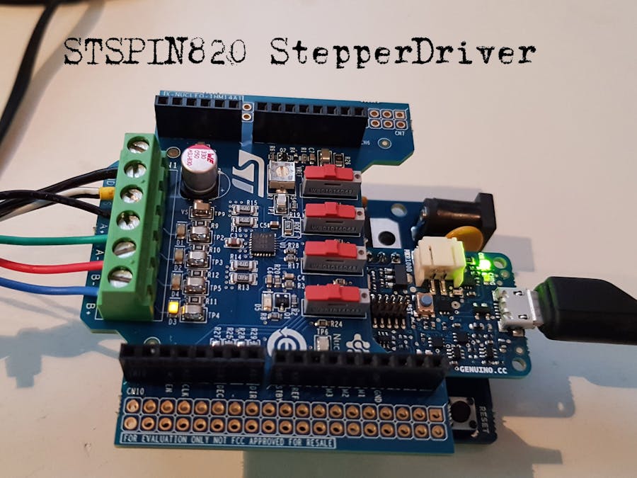
Motor Shield X-NUCLEO-IHM14A1 Stepper Demo with STSPIN820 controller for MKR1000
By JV / 2019
Nem42 stepper motor - 1.8 degrees/step, BiPol (4 lead), max 0.4Amp per coil (37Ohm av resustance = high) -> Sense : 1.65V/Amp => 3.3V / 2 amp
Motor Driver STSPIN820 on IHM14A1 Motor Shield
Function: start stepper left or right by defined stepper Mode
Runs for a cerctain amount of usteps
Shows interrupt Flag.
There is no way to measure the Motor Current with this board (unfortunatly), but easy of drive without software-clocking is very nice.
*************************************************************/
#define DBG
#define FULL_STEP 0
#define HALF_STEP 1
#define QUAD_STEP 2
#define OCTA_STEP 3
#define SIXT_STEP 4
// Define more for 1/32 and 1/64 ,1/28 or 1/256 if you like, (see Datasheet 5.2 page 13)
#define CW 0
#define CCW 1
const int STBY=8; // STBY = Standby\reset input. When forced low the device enters in low consumption mode: all motor-coils are non-current
const int REF=9; // REF = Reference voltage for the PWM current control circuitry. should be 0 for max Vref or PWM-ed (turn R7 pot to 1K)
const int MODE1=0; // MODE = stepper setting : [M1,M2,M3] = 0,0,0 = full step, 1,0,0 half step, 0,1,0 quartestep etc - (see Datasheet 5.2 page 13) Remark : D13 on UNO !!
const int MODE2=12; //
const int MODE3=11; //
const int EN_FAULT=2; // EN_FAULT = input for failure, or forced output . This is the power stage enable (when low, the power stage is turned off) and is forced low through the integrated open-drain MOSFET when a failure occurs.
const int INT_FAULT=1;// EN_FAULT is hard wired to MKR pin 1 for interrupt -> pin 2 does not serve interupt on MKR boards !! (MKR Pin1 = UNO2MKR pinD10 / PA23_TC4-W1)
const int STCK=3; // STCK = Step clock input, ie 1KHz, used vie tone() command
const int DECAY=5; // DECAY = Decay mode selection input. High logic level sets slow decay mode; low logic level sets mixed decay mode - (see Section 5.3 on page 16 Datasheet).
const int DIR =7; // DIR = Direction input
int INT_FLAG=0;
void setup() {
//establish motor driver pins
pinMode(STBY, OUTPUT);
pinMode(REF, OUTPUT);
pinMode(MODE1, OUTPUT); pinMode(MODE2, OUTPUT); pinMode(MODE3, OUTPUT);
pinMode(EN_FAULT, INPUT); // set to monitor Fault
pinMode(STCK, OUTPUT);
pinMode(DECAY, OUTPUT);
pinMode(DIR, OUTPUT);
pinMode(INT_FAULT, INPUT_PULLUP);
attachInterrupt(digitalPinToInterrupt(INT_FAULT), Fault, FALLING);
Serial.begin(9600);
Serial.println("\nMotor Shield X-NUCLEO-IHM14A1 Stepper Demo with STSPIN820 controller for MKR1000");
MotorInit();
}
void loop(){ // Example loops
delay(2000);
INT_FLAG=0;
Serial.println("\nStart Motor Loop:");
MotorLoop(500,1600,CW,HALF_STEP); // (0.5KHz) 2ms step-time, 1600 steps = 4 turns @ 1/2step (200 fullsteps @ 1.8degree = full turn)
delay(6000);
Serial.print("\nMotor on Hold: ");Serial.println(INT_FLAG);
delay(1000);
MotorPowerDown();
Serial.print("\nMotor in Standby ");Serial.println(INT_FLAG);
}
// interrupt routine for EN_FAULT going low
void Fault() {
INT_FLAG=!INT_FLAG;
}
// motor start By setting tone to the STspin820 clock input for a certain time
// Freq - Clock freq, stp = stepper steps, so time (in ms) = 1000*stp/frq.
// stp=0 : no time limit, run forever
void MotorLoop( int frq,int stp,int dir,byte mod) {
digitalWrite(STBY,1); // Wake up Controller
digitalWrite(MODE1,mod&1); // bit0 = mode1
digitalWrite(MODE2,mod&2); // bit1 = mode2
digitalWrite(MODE3,mod&4); // bit3 = mode3
digitalWrite(DIR,dir); // set direction
delay(10);
if (stp != 0) tone(STCK, (unsigned int) frq, (unsigned long) (1000*stp)/frq ); // turn on for amount of step-time
else tone(STCK, (unsigned int) frq ); // turn on, no time limit
}
// power down the motor, set in standby
void MotorPowerDown() {
digitalWrite(STBY,0); // Forced to standby
digitalWrite(STCK,0); // clock zero
}
void MotorInit() {
digitalWrite(STBY,0); // Forced to standby
digitalWrite(STCK,0); // clock zero
digitalWrite(REF,0); // Reference PWM is Zero: R7 pot makes the Vref
digitalWrite(DECAY,1); // Mixed Decay mode
}


Comments