/*************************************************************
Motor Shield Stepper Demo for MKR1000
By JV / 2019
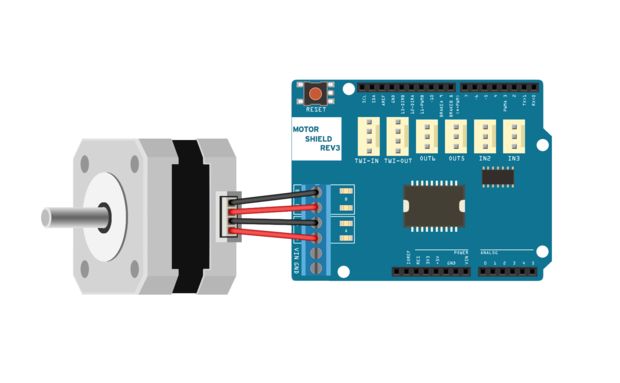
Nem17 stepper motor Astrosyn MY5401 - 1.8 degrees/step, Bidir (4 lead), max 0.75Amp per coil -> Sense : 1.65V/Amp => 3.3V / 2 amp
Motor Driver L298 on Arduino Motor Shield Rev3
Function: start stepper left or right by half-step sequence
Runs for a cerctain amount of usteps
Measures current in a monitor array, to detect stalling : stops drive
Starts with a ramp-up speed to mamimize torque
*************************************************************/
#define DBG
#define MOTORLOCK 50 // 10* % current amplitude volume variantion to signal a lock-up. set level higher at higher motorspeed (lower delay)
#define PEAKFILTER 180 // max peak accepted, to filter out current peaks (wrong measurements?)
#define MOTORSTART 1200 // ammount of usteps the slow start kicks in : 3 turns
const int DIRA=12; // IN1 = DIRA, switches one leg Half-BridgeA
const int BRAKEA=9; // IN2 = DIRA xNor BRAKEA, switched one leg of BridgeA => 1= DIRA 0= #DIRA
const int ENA=3; // ENA = PWMA, enable signal for half Bridge A
const int DIRB=0; // IN3 = DIRB, switches one leg of Half-BridgeB (!! ex pin 13 on Arduino UNO)
const int BRAKEB=8; // IN3 = DIRB xNor BRAKEB, switches one leg of Half-BridgeB =>
const int ENB=11; // ENB = PWMB, enable singnal for Half Bridge B
const int ARRAY=32; // over current Monitoring Array
const int SARRAY=256; // long term array for Debugging purposes : data dump
const int Current0 = A0; // Port for analog current measurement A0 = SenseA
int ShadowArray[SARRAY];
int CounterSh=0;
int CurrentArray0[ARRAY];
int AverageArray0[ARRAY];
int AmplitudeArray0[ARRAY];
int CounterAv=0;;
int CounterAm=0;
int CounterCu=0;
int AvgCurrent=0;
int Lock;
int Sequencer[7][8] ={ // Sequencer[MotorPin][Value] 8 states
0, 1, 1, 1, 0, 0, 0, 0, // DIRA = IN1
1, 0, 0, 0, 1, 0, 0, 0, // BRAKEA high = follows DIRA, IN2 = #IN1
100,700,950,700,100,700,950,700, // ENA PWM, hard coded TCC Timer@24Khz : 1000 = full open 700 = 70% (1/V2)
1, 1, 0, 0, 0 ,0 ,0 ,1, // DIRB = IN3
0, 0, 1, 0, 0, 0, 1, 0, // BRAKEB high = follows DIRB, IN4 = #IN3
950,700,100,700,950,700,100,700, // ENB PWM, hard coded TCC Timer@24KHz : 1000 = full open 700 = 70% (1/V2)
700,700,700,700,700,700,700,700 // uSec Delay per 1/8 Phase
};
void setup() {
//establish motor direction toggle pins
pinMode(DIRA, OUTPUT); //CH A
pinMode(BRAKEA, OUTPUT); //brake (disable) CH A
pinMode(DIRB, OUTPUT); //CH B
pinMode(BRAKEB, OUTPUT); //brake (disable) CH B
// pin 3 PWMA out
// pin 11 PWMB out
Serial.begin(9600);
MotorPowerDown();
analogReference(AR_DEFAULT); // 3.3V internal reference
analogReadResolution(10); // 10 bit resolution is ok, gives 0-1024 value on A0 is SenseA -> 1,65V/Amp => ful resolution = 2 Amp
setupPWMTimers();
//analogWrite(3,255); not used due to Highspeed PWM setup with Cortex0-M0
//analogWrite(11,255); not used due to Highspeed PWM setup with Cortex0-M0
}
void loop(){ // Example loops
delay(2000);
MotorLoop(400,0); // turns 400 usteps CCW = 1 turn
DumpData();
delay(2000);
MotorLoop(1600,1); // turns 3200 usteps CW = 4 turns
DumpData();
delay(2000);
MotorLoop(4800,0); // turns 6400 usteps CW = 12 turns
DumpData();
delay(2000);
}
// motor loop By BITBANGING the Sequence Array,
// 1 ustep cycle, dir =1 -> CCW, dir = 0 -> CW, 400 usteps = 1 rotation
void MotorLoop(int lps,int dir) {
int t=0;
int v=0;
int level=0;
int dly;
int tslow= MOTORSTART;
int ttslow=0;
CounterSh=0; // initialises array counters
CounterAv=0;;
CounterAm=0;
CounterCu=0;
AvgCurrent=500;
Lock=0; // Sense Lock up of motor, clear for start of run
dir=(dir&1)*4; //make it binary and 0 or 4 (4 shift = half cycle step in the sequence array = 90 degrees )
if(lps <0) lps= 32768; // -1 loops makes loops maximum
for(t=0;t<lps;++t) {
digitalWrite(DIRA, Sequencer[0][t%8]); //DISABLE CH A
digitalWrite(BRAKEA, Sequencer[1][t%8]); //Sets direction of CH A
REG_TCC1_CC1 = Sequencer[2][t%8]; // TCC1 CC1 - on D3 50%
while (TCC1->SYNCBUSY.bit.CC1); // Wait for synchronization
digitalWrite(DIRB, Sequencer[3][(t+dir)%8]); //DISABLE CH B
digitalWrite(BRAKEB, Sequencer[4][(t+dir)%8]); //Sets direction of CH B
REG_TCC1_CC0 = Sequencer[5][(t+dir)%8]; // TCC1 CC0 - on D11 50%
while (TCC1->SYNCBUSY.bit.CC0); // Wait for synchronization
dly = Sequencer[6][t%8]+ tslow/4+ttslow;
if ( tslow>0 ) tslow--; // tslow counter for slow (re)start
// read current, calculate Array : est. 500 microseconds
if ( (t%8)==2 || (t%8)==6 ){ // measure Half-Bridge CoilA current, only on max amplitudes in cycle 3 and 7
delayMicroseconds(dly-500); // shorter delay due to processing part of 500us
level = analogRead(Current0);; // read current
CurrentArray0[CounterCu]= level; // move to current monitor window
ShadowArray[CounterSh]=level; // move to debug ARRAY
CounterCu = (CounterCu+1)%ARRAY; // loop counter
CounterSh = (CounterSh+1)%SARRAY; // loop counter
Lock = (int) CalcArray(); // calculate array's and check for overshoot
if ( (Lock > MOTORLOCK) && (t > ARRAY*4) ) t=lps+1; // stop loop: if lock has value: stop, ignore first 128 steps (array not filled)
// else ttslow= Lock; // slow down motor a bit when its peaking
}
else
{
delayMicroseconds(dly);
}
}
MotorPowerDown();
}
// Update Current array calculations
int CalcArray(){
int w = 0;
int tmp=0;
int vol=0;
for (w=0 ; w<ARRAY ; ++w){ // loop array and calculate average of the buffer
AvgCurrent = ( (ARRAY-1)*AvgCurrent + CurrentArray0[w])/ARRAY; // Calc new average
AverageArray0[w] = AvgCurrent;
tmp = abs(CurrentArray0[w]-AvgCurrent)%PEAKFILTER; // calculate deviation, filter peaks out by modulo operator.
vol += tmp; // calculatie volume deviation
}
vol=(1000*(vol/ARRAY))/AvgCurrent ; // scale to average per array-sample relative to average (in 10* %)
AmplitudeArray0[(CounterAm++)%ARRAY] = vol;
return (vol);
}
// power down thew motor, disable all mosfets
void MotorPowerDown() {
digitalWrite(DIRA, LOW); //DISABLE CH A
digitalWrite(BRAKEA, HIGH); //Sets direction of CH A
digitalWrite(DIRB, LOW); //DISABLE CH B
digitalWrite(BRAKEB, HIGH); //Sets direction of CH B
}
// Dump data to serial in xls format semicolon separated
void DumpData() {
int u;
//Dump Array data Shadow
Serial.print("ShadowCurrrent;");Serial.print(Lock);Serial.println(";");
for (u=0;u<SARRAY;++u) {
Serial.print(ShadowArray[u]); Serial.println(";");
}
//Dump Monitor Array data
Serial.print("Current;Average;VolumeDiff; -Lock;");Serial.print(Lock);Serial.println(";");
for (u=0;u<ARRAY;++u) {
Serial.print(CurrentArray0[u]); Serial.print(";");
Serial.print(AverageArray0[u]); Serial.print(";");
Serial.print(AmplitudeArray0[u]); Serial.println(";");
}
}
// Output PWM 24Khz on digital pin D3 and D11 using timer TCC1 (10-bit resolution)
void setupPWMTimers()
{
REG_GCLK_GENDIV = GCLK_GENDIV_DIV(1) | // Divide the 48MHz clock source by divisor N=1: 48MHz/1=48MHz
GCLK_GENDIV_ID(4); // Select Generic Clock (GCLK) 4
while (GCLK->STATUS.bit.SYNCBUSY); // Wait for synchronization
REG_GCLK_GENCTRL = GCLK_GENCTRL_IDC | // Set the duty cycle to 50/50 HIGH/LOW
GCLK_GENCTRL_GENEN | // Enable GCLK4
GCLK_GENCTRL_SRC_DFLL48M | // Set the 48MHz clock source
GCLK_GENCTRL_ID(4); // Select GCLK4
while (GCLK->STATUS.bit.SYNCBUSY); // Wait for synchronization
// Enable the port multiplexer for the digital pin D3 and D11 **** g_APinDescription() converts Arduino Pin to SAMD21 pin
PORT->Group[g_APinDescription[3].ulPort].PINCFG[g_APinDescription[3].ulPin].bit.PMUXEN = 1;
PORT->Group[g_APinDescription[11].ulPort].PINCFG[g_APinDescription[11].ulPin].bit.PMUXEN = 1;
// Connect the TCC1 timer to digital output D3 and D11 - port pins are paired odd PMUO and even PMUXE
// F & E specify the timers: TCC0, TCC1 and TCC2
PORT->Group[g_APinDescription[2].ulPort].PMUX[g_APinDescription[2].ulPin >> 1].reg = PORT_PMUX_PMUXO_E; // D3 is on PA11 = odd, use Device E on TCC1/WO[1]
PORT->Group[g_APinDescription[11].ulPort].PMUX[g_APinDescription[11].ulPin >> 1].reg = PORT_PMUX_PMUXE_F; // D11 is on PA08 = even, use device F on TCC1/WO[0]
// Feed GCLK4 to TCC0 and TCC1
REG_GCLK_CLKCTRL = GCLK_CLKCTRL_CLKEN | // Enable GCLK4 to TCC0 and TCC1
GCLK_CLKCTRL_GEN_GCLK4 | // Select GCLK4
GCLK_CLKCTRL_ID_TCC0_TCC1; // Feed GCLK4 to TCC0 and TCC1
while (GCLK->STATUS.bit.SYNCBUSY); // Wait for synchronization
// Dual slope PWM operation: timers countinuously count up to PER register value then down 0
REG_TCC1_WAVE |= TCC_WAVE_POL(0xF) | // Reverse the output polarity on all TCC0 outputs
TCC_WAVE_WAVEGEN_DSBOTH; // Setup dual slope PWM on TCC0
while (TCC1->SYNCBUSY.bit.WAVE); // Wait for synchronization
// Each timer counts up to a maximum or TOP value set by the PER register,
// this determines the frequency of the PWM operation: Freq = 48Mhz/(2*N*PER)
REG_TCC1_PER = 1000; // Set the FreqTcc of the PWM on TCC1 to 24Khz
while (TCC1->SYNCBUSY.bit.PER); // Wait for synchronization
// Set the PWM signal to output , PWM ds = 2*N(TOP-CCx)/Freqtcc => PWM=0 => CCx=PER, PWM=50% => CCx = PER/2
REG_TCC1_CC1 = 800; // TCC1 CC1 - on D3 80%
while (TCC1->SYNCBUSY.bit.CC1); // Wait for synchronization
REG_TCC1_CC0 = 800; // TCC1 CC0 - on D11 80%
while (TCC1->SYNCBUSY.bit.CC0); // Wait for synchronization
// Divide the GCLOCK signal by 1 giving in this case 48MHz (20.83ns) TCC1 timer tick and enable the outputs
REG_TCC1_CTRLA |= TCC_CTRLA_PRESCALER_DIV1 | // Divide GCLK4 by 1
TCC_CTRLA_ENABLE; // Enable the TCC0 output
while (TCC1->SYNCBUSY.bit.ENABLE); // Wait for synchronization
}


Comments