
Hardware components | ||||||
| × | 1 | ||||
 |
| × | 1 | |||
Software apps and online services | ||||||
 |
| |||||
| ||||||
Control all household equipments universally with one device
Hardware Components:Software Components:- RS232 Terminal Program of your choice
Household equipments with Remote Controls use IR LEDs to communicate. These remote controls use combination of different protocols and codes to transmit commands for a particular action, like powering on/off the device, changing volume, etc. These remote control codes can be programmed and transmitted to imitate the functionality of a remote control.
Procedure:So, we’ve established that we have to control different equipments, which use IR LEDs to communicate, with our device. Firstly, we’ll have to determine the protocol in use by that particular equipment’s remote control. Next, we need to determine the codes corresponding to different actions like power on/off. Let’s start with the learning stage followed by the implementation phase.
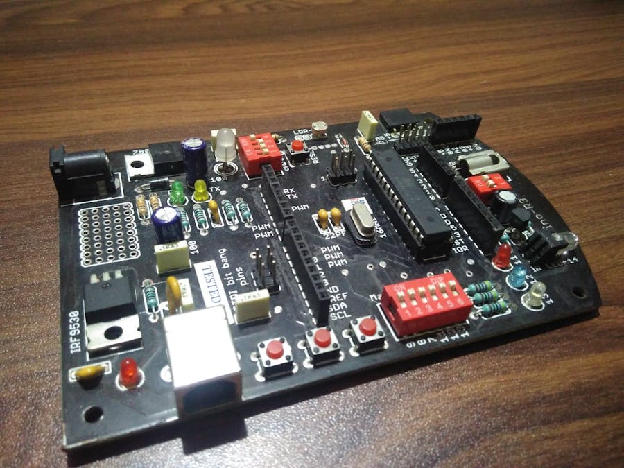
Learning Stage:Induino R3 board has a host of sensors on board which provides loads of scope for experimentation. It also boast a IR receiver and IR LED which we require for this project.
For learning phase, we’ll be using the TSOP SM0038 IR receiver on the Induino board.
- Configure the TSOP IR Receiver for input
- Scan for IR Codes, determine the protocol in use
- Decode control code
There’s a library for IR Remote hosted at SimpleLabs which provides APIs in form of a library^ for this. We are interested in the IRRemote library.
Code for reading the protocol and control code:
/*
 * Code to print protocol and control code received by TSOP receiver.
 * 25/12/2016, Vaibhav Rekhate
 * https://vaibhavblogsite.wordpress.com/
 */
#include <IRremote.h>
#define IR_RECV_PIN 15
IRrecv irRecv(IR_RECV_PIN);
decode_results rxPkt;
void setup()
{
  // Set baudrate to 9600
  Serial.begin(9600);
  // Enable IR Receiver
  irRecv.enableIRIn();
}
void printControlCode(decode_results *rxPkt) {
  int count = rxPkt->rawlen;
  bool valid = true;
  switch(rxPkt->decode_type) {
    case NEC:
      Serial.println("NEC Protocol");
      break;
    case SONY:
      Serial.println("SONY Protocol");
      break;
    case RC5:
      Serial.println("RC5 Protocol");
      break;
    case RC6:
      Serial.println("RC6 Protocol");
      break;
    case UNKNOWN:
    default:
      Serial.println("Unknown protocol");
      valid = false;
      break;
  }
  if (valid) {
    Serial.print("Control Code: ");
    Serial.println(rxPkt->value, HEX);
    Serial.print("Control Code Length: ");
    Serial.print(rxPkt->bits, DEC);
    Serial.println(" bits");
  }
}
void loop() {
  if (irRecv.decode(&rxPkt)) {
    printControlCode(&rxPkt);
    // Resume reception
    irRecv.resume();
  }
}
This prints on the serial port (open Arduino Serial Monitor or any terminal program of your choice).
You can play with this setup, and note down the codes for different buttons on the remote control. Keep this handy as we’ll be using this when we use the IR LED to transmit codes.
Implementation Phase:Now that we have the protocol and the control codes, it’s time we move to the implementation phase. The IR Remote library also offers APIs for transmitting. However, they are generated on the PWM pin #3 of the Induino R3 board. So to use the IR LED on the board, simply connect pin #3 to Analog #0 of the board (see figure 2 below) which drives the IR LED. Remember to disconnect the RGB LED (pin #3) using the slide switches.
Now that we are set, it’s time for the software part. To keep things simple yet configurable, the input is taken from serial port.
Code to take input from terminal and transmit the control code with NEC protocol. As my remote control uses 32 bits and NEC protocol, I decided to hard-code those values.
/*
 * Code to transmit using the NEC protocol the control code taken
 * as input from serial port.
 * 25/12/2016, Vaibhav Rekhate
 * https://vaibhavblogsite.wordpress.com/
 */
#include <IRremote.h>
IRsend irSend;
void setup()
{
  // Set baudrate to 9600
  Serial.begin(9600);
}
void loop() {
  long upperCode = 0, lowerCode = 0;
  if(Serial.available() > 0) // if Serial data is received
  {
    upperCode = ((long) Serial.read()) << 8;
    delay(50);
    upperCode |= ((long) Serial.read() & 0xff);
    delay(50);
    lowerCode = ((long) Serial.read()) << 8;
    delay(50);
    lowerCode |= ((long) Serial.read() & 0xff);
    // Print code to verify input is correct
    Serial.print("Entered code: "); // print the current value
    Serial.println(((upperCode << 16) | lowerCode), HEX);
    // Send control code in NEC protocol
    irSend.sendNEC(((upperCode << 16) | lowerCode), 32);
    delay(100);
    // Flush buffer before starting over
    Serial.flush();
  }
}
Now using your terminal program, send raw bytes to the Induino board. I use Termite as my terminal program as it can handle raw bytes as input*.
Bingo, I input the control code for changing the volume and it works!
Observations:Most of the learnings are from the learning stage (what an apt name 😉). For a particular equipment, all the control codes start with the same pattern mostly to identify which device to communicate with**. For example, for my Philips equipment, all codes start with 0x10EF. Interesting thing to note was that all commands ended with either 0xF or 0x7 or with 0b111 to be precise. So from 32 bits, 16 bits indicated the device code (0x10EF), and the last 3 bits are don’t care. So, we’re left with 13 bits, which form the command and the address pattern as discussed here, but let’s leave the examining part for some other post.
Postlude:Once the codes to perform any action are ready, this device can be used to transmit them. Effectively as we can control multiple equipments with the same device, this can be used to make the dumb devices, smart.
Appendix:^ For sample codes and libraries from SimpleLabs click here.
* Sending raw hex bytes as input in Termite. Open Settings pane and:
- Enable Hex View by selecting the check-box in front of ‘Hex View’.
- Double Click ‘Hex View’ for Hex settings, and set suitable prefix.
- Set append settings to Append Nothing so that only the intended bytes are sent.
- Send hex bytes prepended with the prefix you set earlier.


Comments